Tuesday, January 29, 2019

I2C Bus Blues

Well, it turns out that last week's post titled: "Measurements Back Online" was incorrect. There is currently an issue with the I2C bus that is used for collecting orientation sensor data and also for collecting data from the new ADS1115 analog to digital converter that was added last week. I checked all the pull up resistors for the clock and data connections, and everything there seemed OK. The wiring also seemed OK, and I couldn't find any shorts. After repeated testing, I eventually noticed that the I2C problems only occurred after the PWM output to the rudder was turned on. What's kind of weird was that the problem persisted even if the PWM connection to the rudder servo motor was cut. If I removed the other end of the cable though, the problem went away.

I'm not sure what to make of this yet. I have found some related articles online about PWM sometimes interfering with I2C with certain wiring configurations. Also, the cabling I'm using is kind of long, about 2.5 m from the Raspberry Pi at the front of the boat to the rudder and ADS1115 at the back of the boat. Some possible solutions I can think of to try include:

1. Connect grounding wire in the same 2.5 m twisted pair Ethernet cable that currently has the I2C data and clock lines, as well as the 3.3V line and the PWM line. Currently the ground connection is shared across the boat electronics through other wires, but maybe having a ground wire in the same Ethernet cable as the signal wires will help somehow. This forum thread talks about inadequate grounding as a possible cause of I2C interference from other signals: http://forums.netduino.com/index.php?/topic/3670-can-pwm-interfere-with-i2c/

2. Try shortening the Ethernet cable a little bit. I can probably shorten the cable by a couple of feet and still have it reach. I doubt that will completely solve the problem though.

3. Move the ADS1115 into the same enclosure as the Raspberry Pi and orientation sensor. This would put all the I2C devices into the same small box, with minimal distances for the 100 kHz clock and data signals to travel. Probably this would work, but I really liked the idea of deploying the sensors from the back end of the boat.

There are probably other things to try too, but I can't think of them at the moment. Feel free to comment on this post to offer suggestions though!

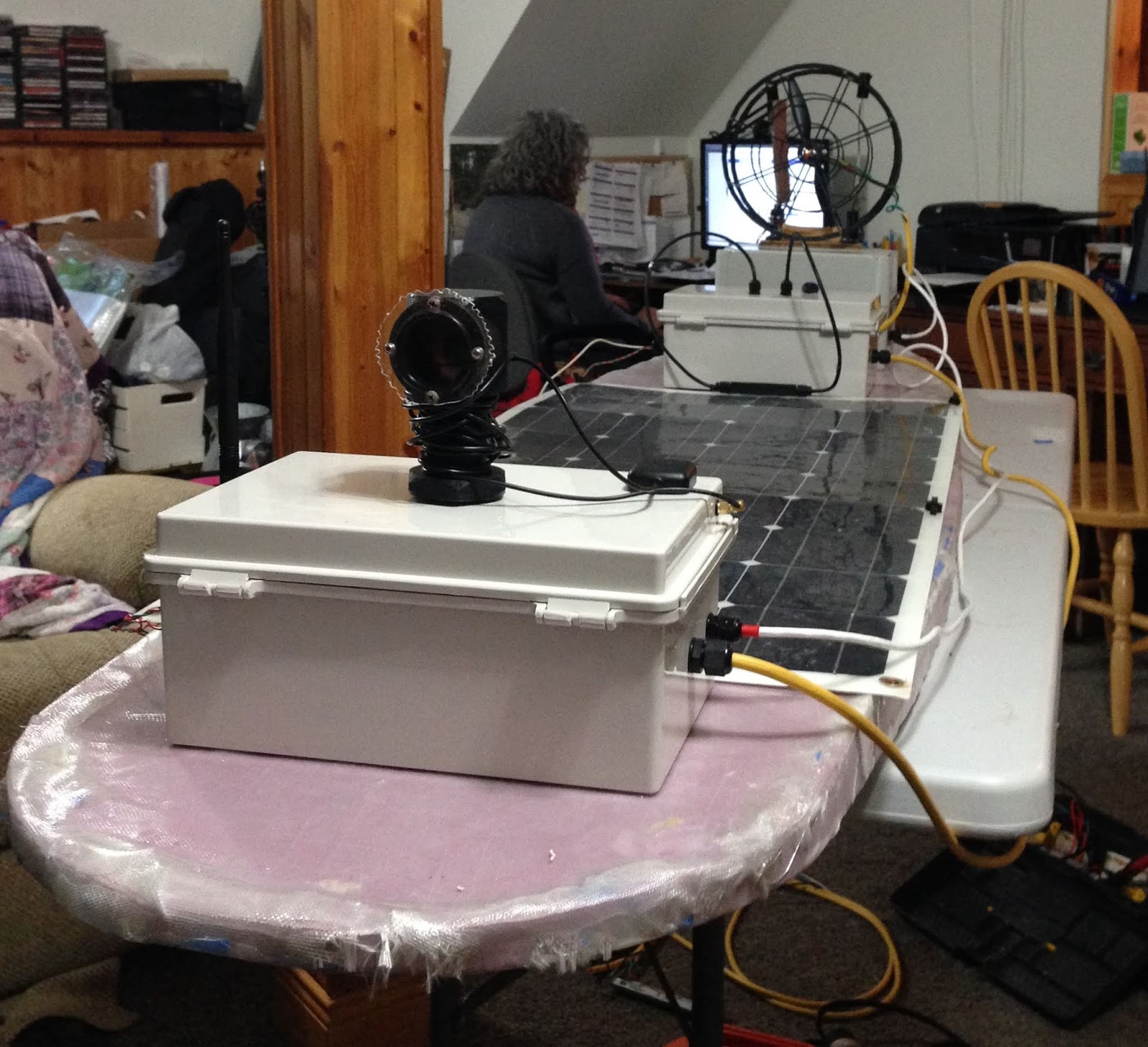
Since every blog post seems to have at least one picture, here are the boat's spiffy new orange handles (at the stern and bow):


I glued down the electronics enclosures with epoxy and also used some of the epoxy for solar panel fastenings and the handles. So maybe now I'll have to paint this version of AMOS orange?

EDIT (Jan. 30, 2019): The issue with the interference on the I2C bus caused by the PWM signal has been solved. The problem was my ignorance of how the wires inside an Ethernet cable are actually organized. The kind I have is organized into twisted pairs of unshielded, color-coded wires (UTP 5E). It would be a bad idea (for example) to put the clock signal for I2C on one half of a twisted pair and the PWM signal for the rudder on the other half. Which is what I did. Voltage from the PWM signal was being induced into the I2C clock line. Switching the PWM wire to one of the ones available that were not twisted with the 2 ITC lines fixed everything up.


Tuesday, January 22, 2019

Measurements Back Online

The replacement analog to digital converter that I ordered last week arrived, and I was able to get it nicely soldered up onto a prototyping board with some screw terminals for the 4 channels of signal inputs (signal and ground for each channel):

The software for collecting data from this board also needed to be re-written, and this ended up taking a couple of days to get right. It works quite well now though; measuring the battery voltage at least gave very nice, stable readings, and it is a bit faster than the old ADC converter. If I wanted to dedicate an extra input on the Pi to it, I could also sample it continuously which would probably be even faster, but it seems quick enough and I have plenty of wires to worry about already.

On my last order to robotshop.ca I added a few extra items to qualify for free shipping. One of these items was the DHT-22 temperature and humidity sensor:


I wired it up and put it in the main enclosure where the Pi and some other electronics are located. I also found some C++ code for it online, that worked OK, but sometimes gave bad readings. This sensor uses just a single wire for data, and requires fairly precise microsecond level timing of pulses in order to read it correctly. A dedicated micro-controller could probably handle it, but timing on the Pi with all its complexity and various threads is not always that precise. It messes up about 20% of the readings, which doesn't really matter that much for a humidity sensor I guess. It's not like the humidity is going to be changing very quickly. If one sensor read fails (timeout or checksum failure), just try again. This sensor should be able to tell the user when it is time to change the bag(s) of desiccant in the enclosure(s). It measured the relative humidity in our basement at 35% today, so no need for any desiccant just yet.


Tuesday, January 15, 2019

Trying To Get Some Sleep

A couple of nights ago I had a dream that I was showing off AMOS to Donald Trump. The 45th president of the United States seemed enthusiastic and impressed. I'm not sure if that's a good omen or a bad omen, probably neither.

I would like to be able to leave AMOS outside soon to test it for long term logging of data in an outdoor environment. With all of the electronic devices that it currently uses, there is a substantial drain on the battery, especially at this time of the year when there are really only about 9 hours of sunlight per day. So AMOS needs to have some way of powering down its various power-hungry components while just leaving some minimal electronics running. As a first step towards this, I created a little circuit with some diodes, a pair of AA batteries, a 1 mF capacitor, and a relay controlled by the microprocessor on the serial wireless link to power down virtually everything (including the Raspberry Pi) whenever there is a gap (two minutes or longer) in the activity detected by the Raspberry Pi. The original intention of this was to work as a means of doing a hard-reset on the Pi if its program crashed or stopped unexpectedly. But the powering down could also be used according to a defined schedule (say for long periods of time at night) in order to maintain a good level of charge on the main battery.

Last week I had mentioned that the I2C on the Raspberry Pi had gone kaput thanks to a brief "touch" of the 5 V fuse with the +12  V battery terminal. Yesterday the replacement Pi arrived, and I was able to plug it in and confirm that its I2C bus worked fine. However, the I2C bus on the analog to digital converter (which was connected at the time of the touch) was not fine. It still did not work at all, and the voltage level on the SCLK line was hovering around 4.7 V, not something you would expect for a 0 to 3.3 V clock signal. So apparently the "absolute maximum" rating of 7 V for the power input to this A to D converter really does mean something. While hunting today for a replacement unit, I came across the ADS1115 from Texas Instruments. This is a similar sort of I2C analog to digital converter, but it is less expensive, offers the same 16-bit resolution on 4 single-ended channels, and also can sample at a whopping 860 samples per second! I think the device that I blew only had 16 samples per second.

I subscribe to a couple of different "Google Alerts" about robotics. In one of these today, I came across a Carnegie Melon University (CMU) web page that featured a number of different robotic projects that they are working on, including a robotic airboat: https://frc.ri.cmu.edu/robots/


They have a really strong robotics program at CMU, so it is sort of a nice validation to see that the idea of a robotic airboat has some merit.

Tuesday, January 8, 2019

Boxing It Up

The last 10 days or so have been spent organizing the layout for the 3 waterproof boxes that are to be mounted on top of the surfboard. One of the boxes is a bit larger and is on the back end. It holds the air propeller and rudders on top, and contains A to D and sensor circuitry inside. The middle box has the battery, electronic speed controller, and solar power regulator, and the front box has everything else: Raspberry Pi, wireless serial module, GPS module, camera, LiDAR, etc.


All of the boxes are watertight (at least according to Amazon) and have had holes of various sizes drilled into them for routing cables. These holes should also be waterproof thanks to a multi-pack of cable glands. The solar panel is held down with some plastic bolts and wingnuts that were 3D-printed and glued into the board. At some point I will need to attach some lightweight plastic tubing to the edges of the board for organizing the cables,  and attach some rope handles to the front and back for carrying or towing.

Right now the big challenge is getting all of the circuitry back to the state where it was with the old beer cooler AMOS. There have been a couple of issues so far, as the layout of power and signal wires has proved to be problematic for control of the rudder; for some configurations that I have tried, the voltage getting to the rudder servo motor is too low (less than 4.8 V) and in other configurations turning on / off the rudder servo motor has resulted in power supply fluctuations for the Raspberry Pi board, causing it to crash. I have decided to try solving this problem by giving the rudder servo motor its own power supply (probably ~ 6.5 V, as it affords a bit more torque than the previous 5.0 V).

The second issue encountered was a short-circuit in the battery box that accidentally shorted out the +5 V fuse on the +12 V battery terminal. The fuse had pulled out of its holder when I was mucking about with wires, and I was surprised to notice an LED on the A to D board flash on, even though the power had been switched off. Later troubleshooting indicated that the I2C bus on the Raspberry Pi had been fried. Possibly also the A to D board (which was connected to the I2C bus) is damaged. A new Pi has been ordered, so once that arrives I'll know for sure whether or not the A to D board also needs replaced. Kind of ironic that the fuse that was inserted into the box to protect the Raspberry Pi happened to be responsible for destroying it. 😕

The total current weight of AMOS, with most of its electronics installed is now 28 lbs, about 8 lbs less than its beer cooler predecessor. I had been hoping for somewhat more dramatic weight savings with this re-design, but oh well. All those electronics and plastic boxes certainly add up I guess. Hopefully the improved hydrodynamic shape will make a big difference in the water. Before getting anywhere near the water though, there are still a lot of electronic hookups and cable routing to do!

Tuesday, January 1, 2019

AMOS's New Year Resolutions

Happy New Year! I thought it would be kind of cool to write some software that could parse all of the AMOS ship logs that I saved throughout last year, in order to get a summary of how far AMOS had traveled. Each ship log is just a text file that saves various parameters and debugging information, including a GPS position that gets recorded every minute. These GPS positions can be used to estimate the total distance that AMOS traveled throughout 2018:


I guess you can't really say much about AMOS's sea-worthiness, given that it has only traveled 31.3 km, but it is a starting point of sorts. In total there were 30 trips made, the longest of which was a 5.2 km out and back trip at Cap Brûlé. Some of those trips were under manual remote control, but most of them were autonomous, with a pre-programmed route. A significant percentage of the trips ended (usually quickly) in a failure of some sort: stuck in seaweed, dead batteries, stuck on rocks, loss of communications, invalid GPS route planning, software crashes and bugs, electrical failures / short-circuits, etc.

Had you asked me back in March how much total distance AMOS would be able to cover in 2018 I'm not sure what I would have said. Maybe 100 km? 500 km? Hopefully more? Given this starting point though, I think that 2019 will need to see some significant improvements. I would like to have everything working reliably enough that I could actually leave it unattended for at least 8 hours. For every minute that AMOS spent on the water this past year, I was either following closely in my kayak or watching from shore, making sure it didn't get "lost" or crash into anything. Unexpected problems were just too frequent to do otherwise. If it can attain a good level of reliability, where it can actually be trusted to function on its own for 8+ hours at a time, it should be able to travel much greater distances. For New Year's resolutions, I would like to see AMOS get 1000+ total km in 2019, with a maximum trip distance of at least 50 km. Reaching these goals is a necessary step in getting a robot that people might actually consider buying.