Tuesday, December 25, 2018

AMOS Got Fiberglassed For Christmas

Merry Christmas! The fiberglass cloth and epoxy resin arrived this past week just in time for Christmas, so I figured that AMOS's new foam board should get a nice coat of fiberglass for Christmas, to protect it from getting any more dings or gouges.

First, I used a bit of polyfilla mixed with a few drops of water to fill in some of the pits and cracks that were mostly on the bottom of the board, then after waiting half a day or so for it to dry, sanded it down:


On Saturday I fiberglassed the bottom half of the board, using some painter's tape to hold the edges of the cloth to the perimeter of the top surface:


My technique was loosely base on a series of YouTube videos on fiberglassing foam surfboards. I wasn't really as careful as I should have been in making sure that the epoxy resin did not exceed the tape boundary. This didn't really hurt anything, but resulted in some of the tape getting permanently stuck to the board. I also wasn't particularly good at keeping ridges and bubbles from forming on the glassed surface. In hindsight, I probably should have been more careful to stretch and wrap the cloth prior to gluing.

Yesterday, I fiberglassed the top half. This part was slightly better, but I still had a number of ridges, especially around the edges of the board:


The important thing though, is that AMOS now has a nice protective coating, and I'm fairly confident that it should be able to withstand collisions with rocks, and be able to be strapped down to the roof of a vehicle without damage. This protection carries a bit of a price in terms of weight though, the weight of the board is now 10.2 lbs instead of the 6.5 lbs that it was initially before adding the coating.


Wednesday, December 19, 2018

First Ever Interview

Last week marked the first time that I have ever been interviewed about AMOS:


Kirsten had interviewed me for a French project that she was doing at school about courage. We initially tried to conduct the interview in French, but it did not go very well; too many pauses, poor word choices, and bad pronunciation. So thankfully Kelly was able to do a great voice-over that made it sound really professional!

This past week I spent a bit of time updating the Boat Captain software for iOS, so that it now has close to the same functionality that the PC and Android versions have. Then my waterproof containers and cable glands arrived, so it was time to tear down the old beer cooler AMOS and build up the new surf-board version. This involves a lot of cable labeling, de-soldering, re-soldering, etc. and it looks like I'm going to be at it for a while.


Wednesday, December 12, 2018

Taking Shape

I allowed the glue to dry for three days under the pressure of my weights. The construction adhesive package recommended curing for 24 hours, but I thought it would be safer to give it some extra time. After that, I made some cuts at the front and back with a hand saw in hopes of improving the hydrodynamic shape:


I think the result was reasonable, given my lack of experience and skill in cutting this stuff. The hand saw did leave some rough looking divots in the foam though, which will require filling with a bit of pollyfilla or similar.


I have also ordered some fibreglass cloth and suitable epoxy which supposedly will not eat away at the foam for covering and protecting the boat surface. Right now the boat is nice and light (about 6 lbs) and the fibreglass will add some weight, but if it works it should be worth it I think in terms of the added protection and better look.

Tuesday, December 4, 2018

The Start of AMOS 2.0

The current monitoring circuit that was begun last week was finished, and software was added for the PC and AMOS to view the amount of current that AMOS was consuming on its +12 V circuit. Also added to this diagnostics display was info on the leak sensor status, and (if a serial wireless link was used) the measured RF signal level in dBm. Here is a new screenshot of the BoatCaptain software for the PC (GPS position and time are incorrect because the boat was in the basement):


In an effort to make AMOS lighter and more hydrodynamic, some EPS pink foam insulation was purchased at Home Depot this weekend to make an inexpensive surfboard base (i.e. as a replacement for the trusty, but slow beer cooler). I had studied a number of online examples from people who had made their own paddleboards from this insulation material and had chosen this one in terms of its clear instructions and apparent usefulness (it seemed to actually work): https://www.instructables.com/id/Paddle-Board/

I printed out a picture of a suitably proportioned surfboard, figured out what the scaled dimensions should be, and then cut out a half-template from 1/4" plywood. This plywood was then used to draw both halves of the surfboard on two 2" thick insulation sheets:


The two halves were then glued together with two tubes of construction adhesive and my entire collection of weights were used to apply pressure. After a few days of drying I'll go around it with some sandpaper to smooth it out. Hannah is convinced that it will be too unstable and tippy, even with fins on the bottom and the weight of the electronics, motors, solar panel, and battery on top. Kelly figures it will probably break apart if I try to strap it to the roof of the van. (It can actually fit in the van, but doesn't leave much room for passengers.) So we will see. Perhaps if we get some warm weather and the pond next door melts I'll be able to try it out.


Tuesday, November 27, 2018

Wireless Work and Resonance Solved

Work continued this week with the pair of RFU220 wireless transceivers. The software for AMOS and the PC are now working pretty seamlessly, so everything that could be done before with a WiFi or cell link can now be done with this serial wireless link. I also soldered up an extra pair of communication lines to the PC transceiver which lets me poll it for additional data, like for example the strength of the wireless connection. That should be useful as a troubleshooting tool when the boat becomes unresponsive and starts floating out to sea. 😉 To allow the link to work with an Android or iPhone device I think I would probably need to add some sort of a Bluetooth low energy dongle, to allow the phone to communicate with the serial transceiver.

Some long awaited spare propellers arrived today, so I replaced the warped and broken one with a new version; here is a comparison of old vs. new:


To evaluate whether or not there was any difference in thrust between the two propellers, I used my kayak straps to suspend AMOS from a beam in the garage, and measured the horizontal deflection distance at full throttle. There was no noticeable difference in thrust between the two, at full speed they both gave AMOS a horizontal deflection of ~ 1 inch. Based on the weight of AMOS (36 lbs) and the suspension distance (~ 4 ft) this translated into a pretty small thrust; no more than a pound. One added benefit of the new propeller though was that it ran much smoother, and there was no noticeable resonance at any speed whatsoever. So at least I was able to remove those lines of code that disallowed any speeds between 3 and 6. The lesson learned from this thrust test is that AMOS needs to go on a diet and slim down (i.e. become lighter and more hydrodynamic) if it actually hopes to use an air propeller for real navigation.

Right now I am soldering together some current sensing capability to the transceiver module on AMOS. I am basically just using the two ends of the ground return cable on the +12 V supply as a sort of shunt resistor and amplifying the voltage between the two ends with a surface mount op-amp that I had from an old project. The eventual goal is to add some software and enough smarts to be able to gauge how much battery power is left or how long it will take to charge given the amount of available sunlight.

Tuesday, November 20, 2018

Employees For a Morning

Last Wednesday Kirsten and Bexie joined me in the AMOS development lab (i.e. our family basement) as part of "Bring Your Kid to Work Day". Their first task was to design and build a boat out of cardboard, glue, and duct tape, and see how "seaworthy" it was in our bathtub. Bexie opted for a surfboard type of design, which used only a couple of pieces of cardboard:

It was quite stable, moved well in the water, and was able to carry quite a few coins of "ballast". It definitely out-performed my boat which was not at all stable, and quickly filled with water and sank. Kirsten's boat was similarly stable, but was able to carry more coins due to its three dimensional construction and increased buoyancy. Here is a video that Kirsten took and edited. She opted to go all out on the video editing 😏:


The second task was to solder some wires from a wireless transceiver (the RFU220SU from Synapse (https://synapsewireless.com/resources/core-technology/)) to a USB-RS232 breakout board. Essentially the goal was to see if we could assemble our own wireless startup kit using $50 in parts rather than the $300 or so that it would cost for a commercial version. After taking two minutes to transfer all of my soldering "know-how" they got to it and did a great job. At first when we tried it out in the Synapse software, the wireless transceiver did not get detected, but I had read somewhere that there was a possibility that the RX / TX labels on the breakout board could be incorrectly assigned, so we tried reversing them and voila, it worked - the software detected the board, and we were able to see the various parameters associated with it.

For the third task, I showed them some sections of code in the Android "Boat Captain" software that I wanted to change over to allow it to specify a rudder angle and propeller speed instead of the left and right propeller speeds that the previous version of AMOS required. They did a great job on this also.

The rest of the week was not as fun without my co-workers, but I did manage to get a pair of the Synapse wireless transceivers working, sending data back and forth between my PC and AMOS at 115200 bps. I also modified the main AMOS software to be able to use this wireless serial link and started modifying the PC version of the "Boat Captain" software to do the same. At some point I would like to do a "range test" of these transceivers to see if they can really get anywhere close to the three mile line of sight range that their spec sheet claims. These transceivers also have a lot of extra processing and I/O capabilities beyond basic communications, eg: A to D inputs, digital I/O, PWM outputs, etc. so the one connected to AMOS could be used for measuring voltages, currents, and even acting as a sort of hardware "watchdog" for AMOS to make sure that it is still functioning correctly. If not, it could execute a hard reboot of the Pi board to get it up and running again.

Tuesday, November 13, 2018

Resonating Vibrations and Magnetic Noise

I didn't get to Woolastook for any field tests last week, but was still able to learn plenty from some simple tests in the pool before its surface froze over a couple of days ago. The first obvious problem was that the cage / support for the propeller, including the air rudders tended to resonate (quite a bit actually) over a certain range of propeller speeds. The electronic speed controller for the propeller uses pulse width modulation to control the speed, and in my software I have assigned an arbitrary scale of 0 (minimum speed) to 10 (maximum speed).  The resonating vibrations begin at a speed of about 3, reach a maximum at around 4.5, and then taper off over 6, completely disappearing at 7. The shaking was so bad at around 4 or 5 that the tip of the propeller collided with something and broke off. I think probably that the cage should be made from aluminum wires or similar, something sturdier than PLA. So I modified the software to just avoid all speeds between 3 and 6 and that took care of the resonance issue.

Additional pool testing showed that the directional control of the boat using the air rudder was a bit swervy. Partly this might be because there is less of a turning moment (with the air rudders) than the boat had before when it could change the thrusts of the water propellers mounted on the left and right (er port and starboard) sides of the boat. But testing out the compass module output in the software, I noticed that there was more noise in the compass heading data when power was applied to the air propeller. More power = more magnetic noise. The cables supplying power to the air propeller were a few inches away from the magnetometer, but they were close enough to cause random fluctuations of a few degrees, which didn't help with maintaining directional control.

So I did a bit more work on the inertial measurement unit (IMU) that I had picked up a few weeks ago, and finished a new software class for it and just today finished integrating it into AMOS's main program. Just turning the circuit board by hand, you can see that the output orientation angles that it provides are nice and smooth; much better than what was obtained with the compass module output. Magnetic interference from powering the air propeller will still be a minor issue for steady-state magnetic heading measurements, but for real-time control of the boat's direction, the gyros should do a very nice job of measuring the dynamic orientation of the boat, allowing the air rudder control software to maintain a steadier course.

Tomorrow is "Bring Your Kid to Work Day" and Bexie and Kirsten will be joining me in the morning to help work on AMOS. One of the things that needs to be decided upon for the next revision is the shape / design of the hull. So we will be building some toy-sized boats out of cardboard and duct tape and testing them out in the bathtub to see how stable and seaworthy they are. Here is the example boat that I made:


I have no doubt that the girls will be able to do much better!


Tuesday, November 6, 2018

A Steerable Airboat

The back end of AMOS now has a pair of air rudders situated behind the propeller fan and cage, driven by the servo motor described last week:


Initially the pivot rods used on both rudders were epoxied on, but one of the first tests of the rudders that I did (with the fan blasting at maximum power) caused the epoxy to crack off the left rudder and send it flying. So instead I drilled some holes near one edge of the aluminum sheet and threaded the rods through those. That seemed to be much stronger than the epoxied connection, although the epoxy on the right rudder survived so  I just left it.

The software was modified a bit to allow for manual control of the propeller power and rudder angle. You can see the results below in this video that my daughter Bexie shot and edited:


With our pool semi-drained for the winter, I needed to be careful not to get the boat moving too fast towards the walls. A couple of times it did collide with the walls, resulting in a small crack to one of the inner rings of the back cage.

Currently I'm editing the navigation and control software to work with the propeller / air rudder combo. It would be good to have a chance to test this out in the shallow cove at Woolastook, maybe sometime next week.

Tuesday, October 30, 2018

All Caged Up

After finishing last week's blog I encountered another long string of 3D printing failures on my own printer. We did have a snowstorm one day, but other days the weather was fine, and I have no idea why the prints all failed. I had thought previously that temperature or humidity could have been an issue but now I'm not so sure. The usual reason for failure was that some extra plastic occasionally leaked out of the block holding the extruder, and molten blobs of the plastic landed on top of the print and cooled, so that the extruder would eventually collide with it, knocking the print loose from the base, resulting in a failed mess.

So I just sent off the front and back pieces of the cage to 3DHubs. By not including any side pieces (I used a bunch of 2 mm diameter metal rods for this) I was able to save a lot on printing costs (cost was less than $100 vs. ~ $400 for printing the whole cage). Here is the finished result:


If you are determined to jam your hand in between the metal rods or between the plastic spokes you can still hurt yourself, but I think it offers a reasonable level of safety, while allowing good air flow.

I decided to make the air rudders (to be mounted behind the cage) out of thin aluminum sheets. Here is a video of one of them epoxied to the servo motor:


At first the servo wouldn't turn and I was worried that epoxy had gotten into the gears, but it was fortunately just some loose wiring. A second air rudder will run in parallel to this one, and be driven by a bit of coat hanger joining the two of them.

I also tried out a new inertial measurement unit this week (the AltIMU-10 v5 Gyro, Accelerometer, Compass, and Altimeter from Pololu Electronics www.polulu.com). So far I've been able to get temperature, magnetic, acceleration, and gyro data out of the thing in all 3 axes at about 50 Hz. I'm not sure yet whether or not it would be a good replacement for the electronic compass (without gyros) that I'm using now. The hope is that it might provide more reliable orientation data for AMOS in rough, dynamic water.

Tuesday, October 23, 2018

The Quest For a Cage

Far too much time was spent this past week trying to figure out how to enclose the air propeller in a protective cage, with a servo motor and air rudders also attached behind the cage. I spent a few days coming up with what seemed like a workable design in OpenSCAD, but when I uploaded the files to 3DHubs I was shocked by the price tag for the work: approximately $1000 CAD. The propeller was almost 10 inches in diameter, so the cage had to be fairly substantial in order to properly enclose it. I was able to reduce the diameter of the enclosure a bit though, and remove some of the material from the sides and back. This helped a fair amount, but the price was still ~ $400 CAD. I would do better to just buy a cheap fan from a hardware store, rip its cage off and epoxy it somehow to the rest of AMOS, the air rudders, and the servo motor. I'm not sure what to do at this point, but I did try splitting up the initial design so that I can print some of the smaller pieces on my own printer. After a few wasted prints (I think the temperature was too low) I now seem to be reliably printing stuff; much better than it had been earlier this year. I'm not 100% sure yet why... perhaps the change in temperature of the extruder or maybe the reduced humidity at this time of year is helping the prints to adhere better to the printer's platform. It will take another day or two to print out the smaller things (pivot joints, air rudders, servo motor holders, etc.) but if these work I may try printing the larger pieces too. I'll have to do it in multiple pieces though and then join them back together somehow.

Here is a picture of the servo motor that I got for controlling the angle of the air rudders:


It is normally used for steering toy remote control cars, but it is supposed to be waterproof, and has a fairly high torque rating: 20 kg-cm, which should be sufficient for controlling the angle of the air rudders. I hooked it up to one of the pulse width modulated (PWM) outputs of the Raspberry Pi and wrote a short program to verify that it turned properly through its specified +/- 90 degree range.

Tuesday, October 16, 2018

Sufficient Air Power

Because AMOS is somewhat susceptible to getting stuck in stringy seaweed, I bought an inexpensive plastic air propeller (for use with remote control airplanes), and an electronic speed controller from Amazon. This past weekend some scrap wood was added to the back end of AMOS to mount it, and some simple test software was created to calibrate and use the speed controller. I really wasn't too sure how it was going to go, i.e. whether or not this little plastic propeller would produce enough thrust to move AMOS anywhere or not.

Here is a picture of  Checkers with AMOS and the new air propeller:


And a video of the propeller in action in our green pool:

https://www.youtube.com/watch?v=NDXu83YbiPo

It was extremely windy when the above video was shot, which likely accounted for some of the rotation that AMOS experienced. At present there are no rudders for directional control, I just wanted to see whether or not the propeller could produce enough thrust to move the boat. For the video, the thrust level was at about 70% of maximum output. This corresponded to a current draw of about 20 A at 12 V, comparable to the maximum amount of power that I used with the water propellers. The battery inside AMOS is rated for a maximum continuous output of 20 A, so I probably wouldn't want to drive it beyond that for any length of time. As expected, there is not as much propulsive thrust exerted by the air propeller, compared to the combined efforts of the two water propellers. However, now that the water propellers are removed, there is less drag in the water. I'm also wondering if a more hydrodynamic hull (perhaps catamaran style?) might also help to reduce drag.

The ribbon extension cable for the camera arrived last week, so that was hooked up and tested to confirm that it worked correctly. I also spent an hour or two searching around the Linux geek forums to figure out how to setup the Pi to automatically connect to any of a number of potential wireless access points. This sounds like it should be easy, I mean PCs have been doing that for years right? But there was actually a lot of conflicting information on the Internet about how to do it on a Raspberry Pi properly. I had tried and failed a few months earlier, and have always been manually editing the /etc/network/interfaces file and rebooting every time I wanted to switch access points. But this time I managed to get the wpa_supplicant.conf file setup properly, so now AMOS can connect to any of 3 potential access points, without the need for editing the configuration file every time.

The next step is going to be to design an air propeller cage (so I don't cut my fingers off) and a motor / rudder system mounted to the cage, behind the propeller for steering. I've been looking at lots of pictures of airboats online, and have some idea of how to do it, but I'm sure there will be some challenges. I also recently purchased a pair of wireless transceivers: https://www.robotshop.com/ca/en/24g-transceiver-rf220su-module.html that claim to have a line of sight range of up to 3 miles, and contain an Atmel AVR 8-bit microcontroller (the same one used in Arduino boards). One of the transceivers will be used on a small mast on AMOS, and besides maintaining a communications link, will be used to continuously monitor the "health" of the main Raspberry Pi board. If the Pi board becomes unresponsive for a set period of time, the smaller 8-bit micro can control a relay that will "hard-reboot" the Pi. The small micro also has pulse width modulated (PWM) outputs, analog to digital inputs, and digital inputs / outputs, but I haven't decided what (if anything) to do with them yet.

Tuesday, October 9, 2018

Airboat Revisited?

On Wednesday of last week I took AMOS out to Woolastook to try out the new navigation software, and see if perhaps it could collect a test sample grid of temperature and pH points in a 200 x 300 m area of the river. Unfortunately the new software for getting faster updates of the yaw angle (from the magnetometer) proved to be too noisy for the boat's simple turn function, so it would usually tend to fire the thrusters somewhat randomly trying to do a stationary turn. This function worked fine in the pool, but under real world conditions it was no good. To compound difficulties, I had also keyed in the GPS coordinates for the corners of the sampling grid incorrectly, so that the boat was always attempting to drive itself back to shore.

That night, the software was modified to use a filtered average yaw angle from the magnetometer, based on the previous second's worth of data. This restored the original functionality of the simple turn function. The coordinates of the sample grid were also fixed, and the following day, the test was re-attempted. Things started off well and AMOS proceeded into the wind towards the northwest corner of the sample grid. It then proceeded eastward to complete the first row of sampling, but started behaving quite erratically as can be seen in the GPS track shown below:


After about an hour of this, it mysteriously died. I think that possibly the software crashed, although there was no record in the ship's log file or any of the Raspberry Pi log files to indicate what might have caused the crash. The ship's log file indicated that the battery level was OK before the crash, so presumably power was not an issue. One possibility is that some wires might have shorted out inside AMOS, causing the Pi to stop running. There is some reason to suspect this, since it was discovered after the fact that the compass module had pulled out of its enclosure and was free to float around inside the boat. It was this floating compass that was responsible for the erratic navigation during the eastward sampling stage. The next day, Velcro was applied to the compass module to hold it in place within its enclosure, and a second log file was created for the shell software that starts the main AMOS program, to hopefully save the exit code if a crash occurs.

The next couple of days (Thanksgiving) were spent at Mom and Dad's cottage, wiring up the new A to D board that arrived from ControlEverything.com. It was pretty close to what I had before in terms of parts, just professionally soldered and put together, so I'm sure it will be more reliable. There were some minor software changes to make for it too... some of the configuration commands were slightly different, and I needed to do some averaging in software to achieve an 18-bit level of precision. So far it seems to be working quite well. The weather didn't cooperate for most of the weekend, but on Monday, the waves were not too bad, so I released AMOS for what was planned to be a short 1 km test. Unfortunately AMOS only went about 75 m north from the shore, and then struggled to move anywhere... eventually the wind (which was coming from the north) pushed it back to shore where I retrieved it and discovered that the thrusters had both become fouled with seaweed, the leftmost one worse than the right. Below are a picture of the thruster with the seaweed in it and the clump of seaweed by itself after I picked it out by hand:


So apparently the new propeller shield is not very effective, at least not for this common variety of seaweed. So today I spent some time googling various types of airboat designs. This one (https://www.cim.mcgill.ca/~mrl/pubs/anqixu/iros2011_boat.pdf) seemed intriguing, and indicated that a vessel of a size similar to AMOS could be driven using air propellers. I ordered some inexpensive drone equipment from Amazon (https://www.amazon.ca/dp/B07C5KYNY7/ref=pe_3034960_236394800_TE_dp_1) so once that arrives I'll attach it to AMOS and see whether or not it can actually push the boat through the water. 


Tuesday, October 2, 2018

Tidying Up The Engine Room

I’m tired of sailing my little boat
Far inside the harbor bar --
I want to go out where the big ships float
Out on the deep where the great ones are.
And should my frail craft prove too slight
For waves that sweep those billows o'er,
I'd rather go down in the stirring fight
Than drowse to death by the sheltered shore.

-- author unknown


Two weeks ago I posted a picture of the inside of AMOS after it had been driven home in the van from a test and some of the components had shifted around a bit:


Although the above picture exaggerated the usual condition of AMOS's innards, it wasn't too far from the usual reality. It had gotten to the point where I seemed to be making repairs to the wiring as often as not, and it was time to straighten things up a bit in order to save time going forward.. 

The enclosures that were designed the week before arrived from 3DHubs, so all of the wiring was painstakingly untangled, de-soldered in some cases, the components placed into their respective enclosures, and then re-wired and re-soldered. By some minor miracle, all the electronics worked as they did before the operation took place. A master wiring technician might scoff at the result, but I think that it is a huge improvement.

Without the cover plate:


And with the cover plate:


A ribbon extension cable is on order for the camera, so that it can properly reach from the outside of the boat to the interior of the box.

I had originally intended to build my own printed circuit board to replace the semi-reliable ADC board (the yellowish brown prototyping board in the top-left corner of the above 2 photos). And one morning I set out to do that, but quickly realized that it was going to take weeks. Surely there was something on the Internet already put together? There actually didn't seem to be very much that was suitable, but I did manage to find this: https://store.ncd.io/product/4-channel-i2c-0-20v-analog-to-digital-converter-with-i2c-interface/ It's only 16-bit vs. the 18-bit that I have now, but its sampling rate is 4 times faster, so by maintaining a running average of 4 samples in the software, I should get the equivalent of 18-bit precision. It also accepts a wider input voltage than what I have now, which should help to simplify some of the signal conditioning electronics.

Lastly, some good improvements were made in AMOS's software for holding a fixed heading while driving forward smoothly. The previous control software was usually able to make the boat move forward at a fixed heading, but it was not smooth, requiring the rapid on / off firing of the left and right thrusters to maintain direction, while sacrificing forward speed. The new control algorithm is smoother and faster, and still keeps the boat following a forward course through the water. It has only been tried in the pool so far, but I hope to have it out in the river soon.


Tuesday, September 25, 2018

A Week of Repairs

Although I had hoped to get AMOS out at least once this past week for more testing, there were a number of repair-related tasks, mostly to do with the turbidity sensor that I wanted to take care of first. I also modified the grid collection software, as described last week, to alternate from East to West, then West to East as it collects points in a grid pattern, and cleaned up some of the other sampling code to get rid of occasional extra unwanted samples that were being collected.

The week before I had filled the turbidity sensor enclosure (read cat-food tin) with epoxy in a futile attempt to make it waterproof. Perhaps a different brand of epoxy, one that you mix together would have worked better. The kind I used required no mixing and was meant to cure when exposed to air, which meant that the bulk of the epoxy within the enclosure remained in liquid form, and then leaked quickly out under small cracks of the enclosure whenever it was tilted. The epoxy also made its way in through small openings in the top of the plastic turbidity sensor enclosure and covered the transmitter, receiver, and various other electrical components. So this week, I slowly picked away bits of epoxy from the turbidity sensor, but eventually discovered that the pins on the connector had weakened and snapped off anyway due to corrosion caused by exposure to water.

So I ordered a replacement cheap-o turbidity sensor and hope to have it in a week or two. It appears to be based on a design that is commonly used in washing machines. I'll have to try to cover it as best I can (duct tape?), and just hope that it doesn't get too wet. I was thinking that maybe by attaching some foam floats to the sides of the "sensor boat" it will lift it up a bit out of the water, and hopefully keep its top a little bit more dry. I also looked into some real industrial quality turbidity sensors and got a few quotes. The prices for decent models that are completely waterproof and capable of operating in sea water (titanium construction) are between $2K and $4K CAD. They also include "wipers" for performing self-cleaning of the optical windows. At the moment (although I'm tempted) there doesn't seem to be much point in buying one of these, as both the cheap $14 model and the $2K+ models have similar analog outputs that effectively look the same as far as AMOS and its software are concerned. Of course the $14 model is not waterproof, nor is it calibrated or guaranteed to be stable. It is also (unless externally shielded) affected by external light (i.e. the sun). But it will do for now.

I tried to replicate an issue with the software that occurred in the test from the week before, in which the software stopped writing to the ship's log after beginning the grid data sampling routine. I ran a number of tests in the pool to try to replicate the same sampling conditions, but was unable to replicate the problem: saving to the ship's log seemed to work fine no matter what.

I also bought a small sheet of rubber from Amazon and experimented with making my own gasket for use with the cheap turbidity sensor and various household containers. This was an abysmal failure. Even when I thought I had something that looked fairly tight, water leaked in immediately. Luckily I didn't waste too much time on it. Any waterproofing on AMOS will need to be bought from others.

While testing the turbidity sensor, I noticed that the A to D board was also glitching in and out. My wiring on this thing is admittedly pretty bad, but I think the root cause of the glitching might have  been a number of damp (blue) desiccant beads that had adhered to the surface and pins of the nearby compass module board. Both the compass module and the A to D board share the same I2C bus, so it's conceivable that communication problems could result from an electrical fault on one or both of these boards. On two separate occasions, cleaning off desiccant from the pins of the compass module brought the A to D board back to life. At no point though was the compass module ever unresponsive, so the desiccant theory is really just a guess.

As a step in the right direction towards better protecting the circuit boards on AMOS, I designed some enclosures and sent them off to 3DHubs for printing. Here is the enclosure that will house the main Raspberry Pi Compute module, the GPS module, the leak sensor, and the two thruster speed controllers:


The enclosures are not waterproof, but rather are intended to organize the boards and wires and keep things from shorting out. They also have lids to help protect against any water that might splash down from above.


Tuesday, September 18, 2018

Fog Vision (or Lack Thereof)

Friday morning was a bright clear day at home, but there was a thick fog hovering over the river at Woolastook. The original plan was to test out both the grid sampling software and the LiDAR vision safety software, but it was immediately apparent that the LiDAR would not work in the fog. Back scatter of light from the water droplets must have resulted in the "false" object distance of around
1.8 m. This required turning off the LiDAR safety flag in the configuration file for AMOS, in order to allow the software to ignore the fog and drive the boat normally. Ordinarily, I guess it is OK that AMOS would not drive in the fog, but I'm wondering if the same problem would also happen with rain, or maybe snow? I suspect it would, which could be a bit of an issue with this particular sensor I guess. Reading briefly on the subject of LiDAR issues with various types of weather, it seems that some hardware is better than others in this respect.

The boat proceeded towards the northeast corner of a 9 x 11 point grid that it was supposed to sample, although it did not quite make it. The software crashed, and the boat veered off to the northeast. When it crashed, the exit code was actually zero, so the software did not automatically restart as it was supposed to. I'll need to find some other way of detecting that a crash occurred I guess. Even if the software did restart though, it would have started back at the original GPS coordinate, which would have taken too long, given that only the morning was available for the test. I have since added a command line option to the program to allow it to continue at the last known step of the previous program instance. Looking at the ship's log later, it seems that the crash was likely related to some code for correcting magnetometer headings using GPS data. The code did not appear to be working correctly anyway, so for now at least it has been removed.

Recent improvements to logging code for the server have shown that numerous entities from the Internet seem to enjoy trying to connect and send data to the server. Typically they do not stay connected for a long length of time, and so far have not caused any noticeable harm, but potentially they could tie up the server, or even issue a random command to the boat that causes it to crash or become unresponsive. To remedy that, I have added a simple password requirement to the server, so that both the boat and the boat captain (i.e. mobile app) need to send this password within 10 seconds after connecting, or otherwise be disconnected. This seemed to work when tested today, as it bounced numerous unwanted connections all day long.

A repeat of the grid test was attempted again today. This time the weather was clear, so it was possible to test the LiDAR safety function. I maneuvered my kayak in front of the boat's path several times, and each time the software would stop the thrusters until I moved out of view. Success!!!

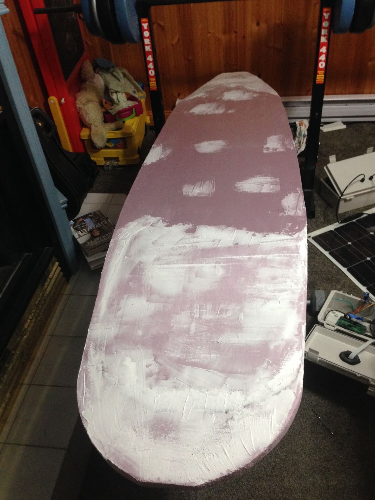
This time the software did not crash, and the boat had time to take one "line" of samples before it became necessary to head back. The next version of AMOS will need to be much more hydrodynamic. It took about 80 minutes for it to drive itself almost 2 km to the sampling grid; and was quite difficult to pull back, as I only allotted 30 minutes for the return trip 😓.


While idling along in the kayak behind AMOS, I realized that the grid sampling software needs to be improved: currently it always uses the same east-west direction for each of the sampling lines. However, it would be more efficient to alternate the east-west direction for each line. Getting out in the boat is always the best way to find improvements. Luckily our weather has been good and the water is still warm, but probably there are only a few weeks of good weather left, so I'll have to squeeze in as many tests as possible!

(NOTE: I believe the curvy blue path in the eastern part of the above image is due to the thruster wires sometimes getting jostled so that they are in close proximity to the magnetometer. Current flowing through the wires interferes with the magnetometer, which in turn causes the software to detect an invalid heading and fire the thrusters erratically, which in turn causes more heading errors, etc. The result is a characteristic, jerky, weaving path. The same thing also happened during some pool testing this past weekend. Some time soon I want to fix up the jumble of wires comprising the innards of this boat.)


Tuesday, September 11, 2018

Not Quite Invincible

To test out how well (or not) the propeller shields worked as a protection against weeds, the following fairly grungy location at Woolastook was selected for a field trial:


As might be expected, this amount of vegetation was too much. The grass and other plant material plastered themselves against the intake grate, effectively stopping the boat in its tracks. At least the grass did not get caught in the propeller though. Here is a picture of a large clump of grass that hung from the propeller shield after the boat had been dragged through the section pictured above:


AMOS was dragged out beyond the grassy area, and then piloted using the Android app for a while, but after about 10 minutes it died abruptly. Checking the ship log afterward showed that the battery was not well-charged at the start of the test (it had been collecting turbidity data all night long the night before), and manually driving the boat near top speed was enough to make the battery drop momentarily below 10 volts, causing the battery management system to kick in and force a reboot of the Pi computer.

Testing over the past few weeks, it was noticed that the GPS signal would sometimes drop out for periods of time. Unfortunately the antenna cable had stopped working (probably the cable had a break in it somewhere) and it was no longer providing any gain so it was replaced with a new $17 model from Amazon. Testing with the gpsmon program on the Pi showed that the new one provided about 3 or 4 dB of gain.

This past week the Android app has gotten a couple of new functions: "homing" and "picture snapshot":


Homing brings AMOS back to the GPS location of the phone and the picture snapshot function tells AMOS to snap a picture using the camera and send it to the phone.

A second test was performed at a different location in Woolastook to test out the LiDAR. The camera was programmed to snap a picture anytime the LiDAR detected an obstacle within 13 m. There were some initial communication problems during this test, which happened to result in a dramatic crash against some rocks:

https://youtu.be/1HZaNorxaYQ

Luckily nothing was damaged, and after pulling the boat away from the rocks, the test continued. The rocks and my kayak were the only things that the LiDAR detected during this test. The water was quite calm and placid though, so the test should be repeated sometime when there are some actual waves, to see if LiDAR reflection off of waves might be an issue. After this test, some code was added to automatically shut down the thrusters whenever an object is detected within 13 m distance.

Tuesday, September 4, 2018

Dirty Pool Turbidity Testing

An unfortunate chemical imbalance in our pool this past long weekend resulted in some algal growth and clouding of the water. Normally this would be cause for disappointment, given the warm weather we have been having lately. However it was a good opportunity to test out the cat-food-tin turbidity sensor. The following is the turbidity voltage data that has been collected since about 4:00 pm this afternoon:


The good news is that the chemical re-balancing that Kelly performed earlier today appears to be working. This was the state of the pool at the start of data collection (~ 4:00 pm):

At the time of this writing it is dark outside, but I'll post a picture of the (hopefully) cleared pool tomorrow morning. Other turbidity readings collected over the past week were usually around 3.6 or 3.7 V when the pool was clear. At Cap-Brulé this past weekend, the turbidity voltage was between 3.35 V and 3.5 V. That was for a moving boat however, which could possibly have some air bubbles interfering with the readings a bit.

Some new software for AMOS was also tested at Cap-Brulé. It changed how the log file was saved, in order to open/close the file for each write, ensuring no log data gets lost in the event of a crash. Also, a secondary program was created to launch the main AMOS program, and then re-launch it if necessary in the event of a crash. Since implementing these changes, no crashes have been observed, but if a crash does happen, AMOS will be ready!

Here is a picture of Hannah holding one of the new 3D printed propeller shields:


These shields are quite light and only contribute a modest amount of drag. They will hopefully protect the propellers from the worst types of entangling seaweed. The water at Cap-Brulé was relatively weed-free this weekend, so a more harsh test will be done tomorrow at Woolastook in an area that has a lot of lily pads.

EDIT: At 07:20 this morning (Sept. 05) the pool is now much more clear. The turbidity sensor is  averaging ~ 3.7 V:


Tuesday, August 28, 2018

Runaway Boat!

A search through the user forums at bluerobotics.com (the manufacturer of the T200 propellers that AMOS uses) turned up some 3D CAD models for propeller shields that users claimed were useful for protecting against weeds, while only contributing a small amount of additional drag. So I sent those off to 3dhubs.com and am expecting them to come in any day now. So no cool swamp air boat designs for now at least.

During the remainder of our week at Cap-Brulé, we were fortunate that the shifting wind and tides moved all the seaweed somewhere else, so I was able to do some more testing on AMOS without having to worry about the propellers constantly getting stuck. I made some changes to the software to improve how remote steering is done using the phone app. Basically, instead of specifying left and right power levels, and hoping that the boat goes straight if the power levels are the same (it never does) I changed it to check the compass heading if the user tells the boat to go straight at a particular power level, and then try to maintain that compass heading and approximate power level using the existing software routines for GPS navigation. Usually the tests of this new software worked pretty well, but a couple of times the software crashed and AMOS continued on into the open water. Even though the program was halted, the propellers still happily turned and sent the boat well away from shore. I tried in vain for about a minute or so both times to re-establish contact, but of course this was impossible as the boat's program was no longer running. So I hastily pulled the kayak into the water and went after it. The weather was quite windy with waves that broke against the kayak's hull and sprayed me in the face. Fortunately the kayak didn't capsize and I was able to catch and retrieve AMOS, probably somewhere around 500 m from shore. I'm still not sure what caused the crashes to occur. The ship's log file was zero bytes both times, as it had not been closed correctly. I should be able to change the software for that to always open and close the file each time the program writes to it... this will slow file logging considerably, but may help to determine what was happening before the crash occurred. Another idea is to create a second program to launch the current AMOS program, and have it automatically re-start the AMOS program if it detects that a crash occurred. Good software should never crash right? But it doesn't hurt to be prepared for a crash anyway.

After we returned from Cap-Brulé there were a few items waiting for me in the mail: the replacement (waterproof) LiDAR sensor (TF02), the 3D printed sensor tow-boat that was described in last week's post, and a 3/4" NPT metal tap for making a threaded hole in the tow-boat. As I had hoped, the replacement LiDAR truly was plug and play. It is a bit bigger and beefier than its predecessor, and can detect objects up to 22 m away. Here is a picture of the new LiDAR mounted atop a small wooden post on AMOS:


Today I was able to create a threaded hole in the tow-boat and then was actually able to screw the top of the pH probe into it for a nice snug fit. I had never done anything like that before, and was pleasantly surprised that it actually worked! I also mounted the turbidity sensor into the central hole, and epoxied a cat-food tin to the top of it to shield it from ambient light. I then did some crude experiments with clear water and water full of loose dirt and twigs (whilst channeling my inner 5-year old) but was unable to determine for sure whether the turbidity sensor was actually working. Usually the readings for the clear water and twiggy, dirty water were the same. But occasionally the reading for the twiggy, dirty water would get very low, so I'm guessing that the water was just not sufficiently mixed and a change in turbidity was only registered when a large particle happened to get between the transmitter and receiver.


These things will be further tested over the next week. 

Tuesday, August 21, 2018

Too Bright, Too Wet, Too Weedy

I tested out the turbidity sensor that I had started hooking up last week, but found that it was greatly affected by ambient light.  As it was only a $14 sensor I had not really expected too much from it. Industrial quality turbidity probes run into the thousands of dollars. Still, it might be able to provide useful data if it were shielded from ambient light; so I designed a small "tow-boat" that can hold the turbidity sensor in an enclosed space with channels that should allow water to flow past the sensor, but also not let much light to enter. The tow-boat also has mounting holes for the pH and temperature probes and was just recently 3D printed by by 3dhubs.com, so should arrive soon:


I'll also need to add a cap of some sort to keep water away from the cable and some plastic tabs that have tiny openings in the sensor casing.

The TF Mini LiDAR sensor arrived this past week, so that was hooked up also, and I ported some Arduino code over to Raspberry Pi to connect to it and start getting data. It worked great, providing object distance data with ~ 1 cm resolution at up to 100 Hz. I figured I would try screwing it down to the front of the hull, just below the line of sight of the camera. As this unit was not waterproof, I applied generous globs of epoxy to the edges and around where the cable plugged in. I wasn't sure whether or not the light from the LiDAR would reflect off of water waves and get detected. A quick test at Cap-Brulé showed that it did indeed reflect off of the water:

It's difficult to see in the above photo, but there is text super-imposed on it ("Distance = 0.74 m") indicating the object distance read by the LiDAR. This was one of 5 pictures taken before the LiDAR stopped working altogether. Apparently my application of epoxy was not sufficiently waterproof, or perhaps water spray leaked in around the transmitter / receiver lenses. Thankfully the same company (Benewake) that makes this particular LiDAR also makes an IP65 waterproof model, the TF02, so I ordered one. It looks like it uses the same data format, so hopefully it will just be plug and play. Probably I should mount the TF02 higher up, perhaps on top of the solar panel in order to avoid sensing reflections off of the surface of the water.

Other testing this week at Cap-Brulé has experienced lots of problems with seaweed. The boat could not go more than about 30 m before getting stuck in a patch of seaweed. Argh. It might be time to reconsider the decision to use electric propellers in the water. Possibly an "air-boat" design would work better. There are some RC boats available such as this one: https://www.youtube.com/watch?v=7mz1_1T-4FY that seem to have plenty of power (~ 500 W) and also seem to be fairly maneuverable. So I'm going to think about it for a bit, and maybe see if I can pick up some parts to make a DIY robot swamp boat.


Tuesday, August 14, 2018

The Weed-Free Strainer Boat

As the summer has progressed, the prevalence of weeds in the St. John River where I have done most of my testing has also increased. Lily pads with their long stems are especially problematic for AMOS's propellers, as the stems seem to enjoy winding themselves around and around the motor shaft, usually causing the motor to stall completely. From what I could read, this problem seems to be universal for all types of propeller driven watercraft. Some larger motors use a "cutter" disc on the shaft, with a sharp outer edge that serves to cut through entangling vegetation. Many of the smaller handheld electric motors (for scuba diving or recreational swimming) use a plastic cage or basket around the propellers, which also helps protect the user's fingers.

Hannah and I took a trip to Walmart to look for suitably sized kitchen strainers that might help to protect the propellers on AMOS from weeds. For a first try, we selected a pair of strainers that had a fairly fine stainless steel mesh. These would be excellent protection against weeds, but I was a bit afraid that the fineness of the mesh would limit the flow of water through the propellers and produce too much drag. I zip-tied and duct-taped the pair of strainers to the mounting U-bolts of AMOS and tested it out in the pool. The initial test was pretty disappointing, as AMOS was quite sluggish. Its top speed was probably less than half what it was without the strainers mounted.


As can be seen in the above photo, the strainers had a plastic "lip" that would be quite useful if you were using them for their intended purpose on the edge of a sink. However this lip was dragging me down. Literally. So I hacked it off with a hand saw, and re-tried the pool test with the lip-less strainers. This time the boat did move faster; about half of its full speed without strainers attached. Perhaps these could be useful for a really weedy area, but I think I could probably get away with more of an open cage type concept, and still have pretty good weed protection.

This week has also seen incremental improvements in the software algorithms used for detecting objects in the water. As expected, this work has been somewhat slow and difficult. I'm working with a set of about 3700 still images that I recorded from an outing on the St. John River. Most of the images don't have any objects in them, but a number of them feature me kayaking in front of AMOS. If the kayak is not too close to the horizon line, it does get "detected" most of the time. The biggest problem at the moment is figuring out how to filter out all the "false positives" that arise from water droplets, shadows, sun reflections, etc. This is a pretty good challenge, but not a hopeless one I think. I think there is still lots of room for improvement in the algorithms that I am using for object detection.

The Mini LiDAR just arrived in the mail today, so I hope to have that hooked up soon and working in conjunction with the camera. I also almost finished hooking up the turbidity sensor this morning. There is a real mess of wires in AMOS now, so simple electronic hook-ups are not quite so simple anymore!


Tuesday, August 7, 2018

Time Away From AMOS

We did a family road trip vacation to Toronto this past week, so I did not have much opportunity to work on AMOS. After returning home and checking to make sure that AMOS was still powered up and working, I was alarmed to see that it was neither powered up nor working. In fact, the battery was completely dead. Connecting the battery terminals to a wall charger for an hour brought it back to life, but the battery icon on the solar charger was flashing ominously, and I was pretty sure I hadn't seen it do that before. The battery voltage was ~ 12.6 V, so if the solar charging were working, I could expect the voltage to climb up to ~ 13.7 V in an hour or less, as the sun was shining brightly at the time. After an hour, the battery voltage still stood at 12.6 V, and the battery icon was still flashing. So something was wrong. I tore apart the "waterproof" connector that was used for the solar panel cables, and confirmed that the crimped wires in this connector were badly corroded. Again. This was the second time that my solar panel crimped wire connections got corroded and were no longer were able to conduct enough electricity to charge the battery.

This time I just made a solder connection with some heat shrink and duct tape to cover up the join. Hopefully it will last a bit longer than my crimped wire connections. I guess time will tell.

A couple of weeks ago I received an interesting promotional email about a couple of different low-cost LiDAR modules. Object detection using a camera-based system seems like it will probably work reasonably well most of the time, but any truly autonomous vehicle should have redundant systems in place to make sure that it doesn't smash into anything. Autonomous cars typically use a combination of cameras, LiDAR, and radar (see for example: https://www.sensorsmag.com/components/three-sensor-types-drive-autonomous-vehicles). The simplest of these was the TFmini LiDAR module (https://www.robotshop.com/ca/en/benewake-tfmini-micro-lidar-module-12-m.html) available for ~ $50 Canadian:

Unlike some of the higher-end LiDARs, this one is just stationary, and has a directional beam width of about 2.3 degrees. It can detect objects up to 12 m away, although in an outdoor environment, that figure goes down to about 7 m I think. It provides updates at 100 Hz, so if it works well I could probably set it atop a pan-tilt module and use it to find a "point-cloud" of objects in the immediate vicinity of AMOS. It also uses 3.3 V logic levels for communications, same as the Raspberry Pi which should make the wiring requirements relatively painless. I ordered one from the robotshop.ca and hope to have it in about a week. I'll probably set it on top of the camera housing and use it to look for obstacles in the immediate forward path. Adding a bit of simple logic should help to keep the sides of our pool from getting robot dents. 😉


Tuesday, July 31, 2018

Obstacles in the Water

Having eyes, see ye not? and having ears, hear ye not? and do ye not remember?
(Mark chapter 8 verse 18, King James Version)

Taking pictures or video with a camera is one thing, but interpreting meaning from those images is quite another. I attempted to read some literature on image recognition and obstacle detection, and got a few rough ideas from it, but nothing that really jumped out as a straightforward solution to the problem of how to detect obstacles floating around in the water, within the camera's field of view.

Since last week's approach of looking for color transitions to find the coast / horizon line seemed to work pretty well, I tried out a similar method of looking for large-ish deviations in color properties of 10x10 blocks of pixels to see whether or not a particular block of pixels might correspond to an object floating in the water. So far I have not tested out the approach on a wide variety of images, but I'm hopeful that by refining the algorithm it might prove to be useful. Below is a screenshot taken from a Windows program that I have been working on for collecting and viewing image statistics and testing out various object detection algorithms. The 10x10 blocks that corresponded to a floating object (i.e. my kayak) appear as small white squares:


We are going on a family vacation to Toronto this coming week, and although I am not permitted to bring AMOS with us in the van, I'm hopeful that I will still have some time to work on various object detection schemes whenever I get a bit of a break from the driving.

Tuesday, July 24, 2018

Red Lines on the Horizon

Not really too much to write about this week; I took AMOS back to Woolastook to capture some video footage:

https://youtu.be/1oR1ij-ENcQ


AMOS got caught in river grass a couple of times during the first part of this test. I'm going to have to figure out some way of shielding the propellers so that doesn't happen...

Later, I applied the feature detection (https://youtu.be/Q59GczzmsyY) and edge detection (https://www.youtube.com/watch?v=_Jexqwt0XSQ&feature=youtu.be) algorithms to the video frames to see how they worked for detecting features. As expected the features were quite susceptible to reflections and splashing in the water, but still might prove to be somewhat useful, perhaps if some form of filtering were used to remove features that don't actually correspond to obstacles in the water.

As a first step in obstacle detection, I worked on finding a way of figuring out where the horizon or coast line was in the various images. Then once that is found, other features can be considered important (i.e. obstacles) if they are below the horizon line.

Basically I looked for a color transition to indicate where the water ended and the trees / bush / sky began. I did this across the width of the image, and then found the linear line that matched up best with the found transition points. In most cases (I think > 90%, and close to 100% in open water) the horizon line was found correctly, even when there were other objects in the image, such as my kayak in the picture below, although the process used to find it was a bit computationally intensive, requiring anywhere between 0.2 to 2.5 seconds to find for each image.


The algorithm for finding the horizon / coast could still sometimes be fooled by reflections, or by large objects in the immediate foreground, including water droplets on the camera's Plexiglas window:


EDIT: Here is the video of the complete test with horizon lines added. Looking at the video, I can see that there are some issues when the waves are high and / or the sun is shining directly at the camera. Otherwise, in open water, the algorithm seems pretty good:

https://www.youtube.com/watch?v=P57pHC5y7lM&feature=youtu.be