Tuesday, April 3, 2018

It's All About The Printing

The 3D printer showed up last Thursday, so I dove into the poorly translated instructions and got to work trying to assemble all 300 or so pieces of it. For the most part, I was able to understand the intent of the instructions, but there were a few instances where things were unclear, or just didn't seem to make sense. For these, I found a pretty good video on YouTube that was able to fill in the gaps.

Although others claimed to have assembled the printer in about 6 hours, I'm quite sure that it took me at least 12 hours. I guess you could say that I was being careful. Finally on Easter Sunday I had it all put together, installed and configured the software, read through the user guide, and was ready to go. The printer only came with a few grams of filament, so I didn't want to waste any time on the example models that came with the software, and instead opted to build my own using openSCAD (http://www.openscad.org/). Since the cable penetrators that I bought to go through the hull of the boat were too short, and I wasn't able to find any online that were long enough (stem needs to be ~ 1.5 inches to get through the insulation) I thought it would be a good idea to make my own. openSCAD is pretty slick, especially if you're used to scripting or programming. I was able to make a simple function call to create a metric M16 screw, and then a 2nd function call to create a hollow 8 mm hole down the middle of it. The model looked great! I then exported to an STL file, brought it into some 3D printing software (Cura), re-saved it as a GCODE file, and then issued the command to start printing.

Before all this, I had eye-balled the heating bed to make sure that it appeared to be level and that the nozzle head was pretty close to the bed surface. Rookie mistake. My first print was a strange jumble of filament in the center of the bed that got pushed around randomly by the nozzle head. So I used the recommended technique of placing a sheet of paper on the bed and moving the head over the surface of the paper to see that it just barely touched everywhere. This seemed to help, although my next two prints (of two separate models on different parts of the bed) also failed... in retrospect I think this failure might have been due to a position error, caused by one of the belts being too loose. Eventually, after midnight I was able to get a not too bad looking penetrator screw. It looked like it was slightly squashed though, again probably due to the loose belt. Tightening the belt the next day seemed to result in better print symmetry.

On Monday I moved the printer out into the playhouse:


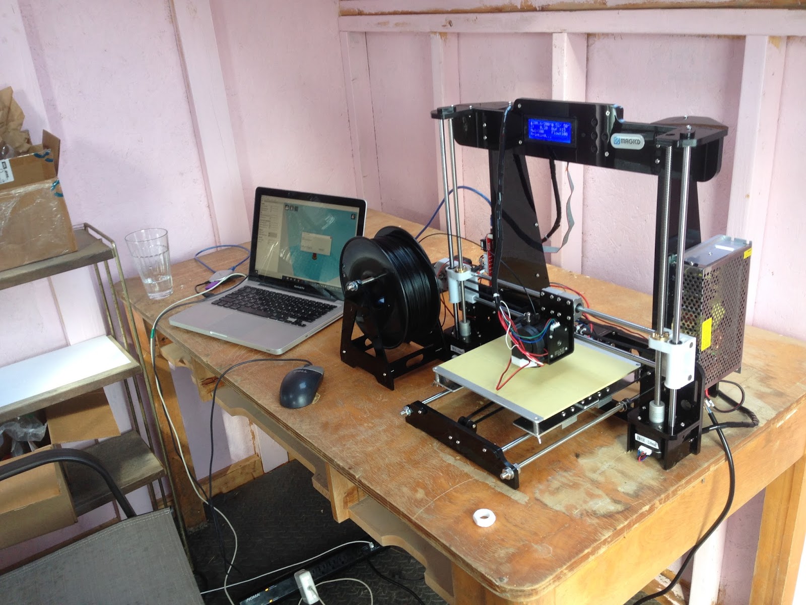
My first couple prints out there did not go particularly well. Tightening the belt improved the symmetry of the modeled screw, but the parts of the screw that were more than about an inch from the heating bed were fairly weak, and tended to tear apart when stressed or torqued with a nut. I think it might have been too cold (~ 10 deg C) in the playhouse. So I tried using the printer's own packaging to insulate the printing volume a bit.


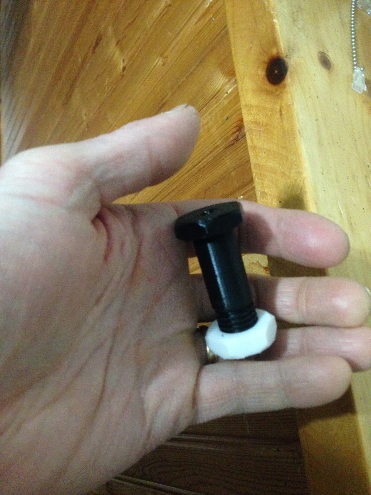
This seemed to do the trick, and  I was able to get some better prints, but still not quite strong enough to actually tighten a nut over it. After shortening the threaded section of the screw, and reducing the hole diameter to 6 mm, I was finally able to make something useful:


Now I'm creating models of parts that will make up the framework for holding the solar panel on AMOS. As these are larger parts, they will require about 5 hours each to print... so a little bit longer between iterations!

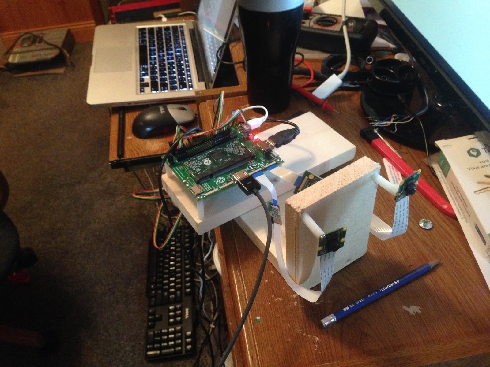
While waiting for stuff to print, I also started work on a sort of generic server program for AMOS that would allow it to receive TCP/IP or Bluetooth / serial commands from a host controller.

EDIT (April 4, 2018): I think I can dispense with the ridiculous box around the printer; I was able to do a number of good prints today at an ambient temperature of ~ 0 degrees C. Suspending the filament reel from a beam in the ceiling seemed to greatly improve the quality and precision of the prints, as the reel was much more free to rotate, and the filament didn't get snagged on anything.

Wednesday, March 28, 2018

The Pretty Print Shop

For a birthday present, my parents gave me some money to buy a 3D printer: I'm getting the "MagicD A8 RepRap 3D Printer" from Amazon. I'm hoping to use it to better organize the jumble of electronics and interconnecting cables that this project is starting to accumulate, and also find some way of making a structural framework that securely connects the solar panel to the boat. It should also come in handy for building a structure to hold the camera boards, as I discovered this week that my crude vision algorithms are highly sensitive to misalignment of the camera boards (one screw per board into a block of wood didn't really cut it).

I read that this printer in particular is a bit noisy, and like any 3D printer needs to be in a place where it will not get disturbed. For that reason, I decided to clean out my daughters' old playhouse and move an old table into it, to hold the printer. I'm a bit worried that it might be too cold, at least for the next few weeks but other users have claimed that it should work OK (at least with the default PLA filament) if you build a bit of an enclosure around it to keep the air around the printer at a reasonable temperature. And during the daytime, it might be warm enough in there anyway.


 This past week I was able to get GPS data into the Compute module with only a few minor hiccups along the way. The module I was using (https://www.seeedstudio.com/Raspberry-PI-GPS-Module-p-2731.html) could be used over USB, so to keep things simple I hooked it into my 4-port Belkin USB hub. Unfortunately though the hub is not a powered hub, i.e. the only power it supplies to the 4-ports comes from the USB bus itself, so maybe something like 100 mA total spread around the 4 ports, I'm not sure. Anyway, the GPS module's spec sheet mentioned that it required at least 100 mA for startup, so I guess I shouldn't have been too surprised that the Compute module completely failed to detect it at bootup. At this point, I figured it couldn't hurt to just try connecting the 5 V available on my I/O board to the GPS module, while leaving the USB cable intact. This resulted in a red LED turning on on the GPS module. I then installed the recommended GPSd client software (http://www.catb.org/gpsd/) and tried to run one of their sample programs. No dice. The LED was still on, but the program said that it couldn't get a satellite lock. Some quick Internet research explained that the first time a GPS tries to get a lock or fix on the orbiting satellites can sometimes take over 10 minutes. So I took the dog for a walk, and came back an hour later to check on it. Still no luck and no lock. More careful study of the spec sheet indicated that although the main chip on the board had an internal antenna, it was really better suited to outdoor operation. So maybe there just wasn't enough signal in my basement? I carried the setup upstairs into our living room and set it near the window, hoping that would be good enough. It wasn't. I then brought the thing outside, and sure enough that red LED that had been solid the whole time suddenly started flashing once per second. I left it outside and logged into it using PuTTY and sure enough it was now providing latitude, longitude, and signal to noise ratio for the satellites that it was receiving. I also tried compiling and running some other GPSd sample C++ code and it too worked great. The GPSd project won the first "Good Code Grant" from the Alliance for Code Excellence, so it should serve me well. Sometimes adding things like this feels a bit like "standing on the shoulders of giants".  I've ordered a magnetic mount GPS antenna so that I can keep the GPS electronics on the inside of the boat. Hopefully the magnet won't mess with my compass too much!

I also made an effort to try to get the cell modem (https://itbrainpower.net/micro-3G-shield-module-du3G/3G-UMTS-micro-shield-board-module-RaspberryPI-Arduino-d-u3G-presentation.php) working too, but fell a bit short in that regard. I signed up for a $10 / month data plan on the weekend, and plopped the SIM card into the module, but again the Compute module failed to detect the board over the USB connection. This time, my more careful read of the datasheet revealed that in fact the USB connection was only used for communications, i.e. not power. For power, this thing actually requires +4V. Not sure if +5V would have worked or not, but at ~ $100 for the modem I didn't want to chance it. Ordered a +4V supply from Robotshop for a few dollars instead.

It turns out that the water tight cable fittings that I bought for getting cables in and out of the boat are too short. There is actually about an inch-thick layer of Styrofoam housed inside the yellow plastic shell of the boat. So I'll need to see if I can find some longer ones I guess.

Finding a suitable depth sounder for the boat has been surprisingly difficult. Pretty much all depth sounders that you can buy seem to be fish finders, with portable graphics displays. You can get some that are kind of cheap (< $100 knockoffs) but they don't seem to have NMEA data outputs that would allow me to "see" the data. The good fish finders with NMEA outputs seem to cost ~ $500 or so. Ugh. I did happen to find this standalone transducer with a NMEA output (http://cruzpro.com/active.html) that only cost about half that. It's from New Zealand; I'm waiting to hear back from their Canadian distributor about buying it.

Wednesday, March 21, 2018

Solar Power: Vroom Vroom!

So now that the solar panel, battery, and solar charge controller had all arrived, there were really no excuses left. It was time to hook everything together, see if the battery would charge properly without exploding or starting a bad fire, and see what these T200 Thrusters (http://docs.bluerobotics.com/thrusters/t200/) were really capable of.


This past Saturday was a clear crisp day, about -10 °C, perfect for testing out charging of the new battery (Dakota Lithium 12 V, 10 Amp-hr https://www.dakotalithiumbattery.com/12-v-10-ah-lithium-battery). Everything seemed to go well. The voltage jumped immediately from about 12.6 V to 13 V or so, and then steadily climbed throughout the afternoon until it reached the pre-programmed limit for the charger of 13.7 V. No fires or explosions, so far so good.

The next couple of days were spent building something of a crude wooden framework around AMOS for supporting the solar panel and possibly the thrusters as well.


The framework is not done yet, but if it works I'll make a better one out of plastic or aluminum.

On Monday, I finished up some code for the electronic compass module (https://www.robotshop.com/en/lsm303d-3-axis-accelerometer-compass.html). At first I was worried that it would prevent the cameras from working, since it was using the first I2C channel on the Raspberry Pi Compute module, which also happened to be used by the graphics processor for the cameras. Fortunately though, switching to the 2nd I2C channel worked fine, and did not interfere with the cameras (er the remaining working camera). It would be possible to try to calibrate this thing, but it appears to work well enough just by normalizing the two's complement digital outputs, so that you get acceleration and magnetic vectors in 3D, which can then be used to compute the device orientation (i.e. roll, pitch, and heading angles). The heading seems reasonably accurate when the device is close to horizontal, so it should be good enough for my navigation purposes. It won't matter too much I guess if AMOS heads off in a direction towards its intended target that is 20 ° or so off... by continuously collecting GPS data, the desired direction to the target can be refined and it should still arrive at the correct location.

Now back to the T200 thruster: yesterday had some hours of frustration initially, as the GPIO pin I was using to control the thruster speed did not seem to be working. Eventually I figured out that the electronic speed controller for the thruster (http://docs.bluerobotics.com/bescr3/) was pulling the output of my Compute module GPIO pin high all the time, i.e. the output from the Compute module was too weak. So it looks like the previous issue with the ill-advised camera repair may have damaged more than just the camera interface... perhaps the entire 2nd bank of GPIO has gone bad. Anyway, switching over to a GPIO pin from the 1st bank worked fine, with an impressive level of thrust when the output was cranked up. The output was fairly jerky and inconsistent though, stemming from the fact that the Raspbian operating system is not real time, so it is not really possible to control the output of a GPIO pin with software to microsecond precision. Fortunately though, the Compute module has a couple of PWM outputs that are perfectly suited to driving this sort of motor controller. Switching the software over to use these instead worked quite nicely, allowing for nice smooth control of the thruster speed. Here's a short Youtube video of a 5 second blast on one of the T200 thrusters: (https://www.youtube.com/watch?v=DUQfTLgzaeM) The video doesn't quite do the thruster justice, you really need to hold it in your hand to get a feel for how much force it exerts. Suffice to say that 2 of these things on the back of the boat should be enough to drive it through some pretty strong seas!


Wednesday, March 14, 2018

9 Days In

So it has been 9 days since I switched to half-time at my regular day job and half-time on AMOS. Well actually it's working out to be significantly more than just "half-time" on AMOS, since a good chunk of my evenings have also been spent sourcing parts and trying to figure out the best possible way to put all this stuff together.

Some progress has been made over the past few days, albeit with a bit of a setback last Thursday: the day before I had written some test code for a sort of crude object detection algorithm, using image data from the two Raspberry Pi cameras. That evening I had re-drilled a hole for mounting one of the cameras, while the camera was still mounted on a post in its old hole. Very bad idea!!! Never drill next to a circuit board with tiny little parts if you can help it. Some small component (possibly an inductor or a zero ohm resistor?) fell off the board and was lost forever. I attempted to repair it myself, the next day, but ended up accidentally shorting out a connection (which I believe) fried the camera interface circuitry on my Raspberry Pi Compute module. So crap. Anyway, this required ordering both a new camera and Compute module. Hopefully they will be here soon.

I also got some code written for testing out a number of different things:

1. Code for turning on thrusters and controlling their speed and direction. Right now I have it limited to about 50 W per thruster, well below the maximum possible 350 W that they are capable of. This is a fairly small boat with limited power resources (10 Amp-hour battery) so I think 50 W per thruster is probably reasonable. Can't wait for the battery to arrive so I can try them out :-)!

2. Leak sensor code: this was pretty simple and worked as expected... I used the SOS leak sensor (https://www.bluerobotics.com/store/electronics/sos-leak-sensor/) from BlueRobotics and just had to monitor a GPIO pin to see if any of the sensors had gotten wet. A couple of drops of water on one of these little disc sensors caused it to swell up and grow (kind of like those kids toys that expand in water) and it must have changed its impedance or something because the digital output of the SOS leak sensor changed right away.

3. Code for sending SMS text messages: for this I used a service provided by Twilio (www.twilio.com). It was pretty simple to get going... basically I got a free trial account from Twilio which gives me a local phone number that can be used for sending and receiving SMS text messages. I think it can even do voice calls too, but I won't be using it for that. I'm not sure if the Twilio account will still be required once I have a cell modem up and running with actual data service, but it works great for now with my Wifi Internet connection.

A crude bathtub buoyancy test of the AMOS boat (beer cooler) showed that it will ride pretty high in the water if there isn't much weight in it. With 30 lbs worth of dumbbells inside, it sat a little bit lower, but tended to list to one side a lot if the weights were not well balanced. 

Last night I spent some time in the garage cutting out strips of plywood, with the intention of building a framework of sorts for supporting the 100W flexible solar panel. If possible, I would like to also mount the thrusters on the same framework and hopefully avoid drilling holes in the hull of the boat. Some holes will inevitably be required for cabling and the cameras, but these could be above the waterline, and would not be subject to significant stresses, such as might occur from the thrusters.

Lastly, I have ordered some more electronics components:

1. Micro 3G/GSM Shield for Arduino & Raspberry Pi ($120 Cdn)
2. Raspberry PI GPS Module ($47 Cdn)
3. LSM303D 3-Axis Accelerometer and Compass ($10 Cdn)

Just this morning I started writing some code for the LM303D; planning on connecting it to the I2C interface of the Compute Module. There's a lot of functionality packed into that $10 board, although I'm not sure how accurate it will be; my experience with other magnetometer-based equipment seems to be that you are "doing well" if you can achieve something like +/- 10 degrees of heading accuracy. With a working GPS though, this hopefully won't be too much of an issue. 


Sunday, March 4, 2018

Starting Tomorrow!

So tomorrow I officially switch over to half-time employment at my regular day job (software developer at Measurand Inc, www.measurand.com) and dedicate the other half of my day to development work on AMOS. The plan is to spend mornings at home, and afternoons at Measurand, but that may get changed around some, depending on what is going on. It's going to be a little bit weird at first I think, but I'm used to doing after-hours contract work and personal projects at home, so probably not that weird. The money thing could result in some stress after a while, we will see. I canceled my bi-weekly RRSP contributions so that will improve the cash flow situation a bit, plus I'm still doing a bit of after-hours contracting work, so hopefully the savings won't suffer too much.

Some more money was spent on parts last week, with the following things ordered:

1. ebay:
12v  10 Amp-hour Dakota Lithium LiFePO4 Battery  ($99 + $30 shipping)  BlueROV (see below) powers an entire ROV with 6 thrusters off of a battery that is only slightly bigger than this, so I'm hoping this one should be sufficient for AMOS, which will only have two thrusters.

2. Amazon:
ALLPOWERS 100W 18V 12V Flexible Solar Panel  ($215 Cdn.) It's supposed to be suitable for RVs and boats.

ALLPOWERS 20A Solar Charge Controller Solar Panel Battery Intelligent Regulator with USB Port Display 12V/24V  ($26 Cdn.)


3. BlueRobotics:
Two T200 thrusters (and two speed controllers) ($388):


Plus an SOS leak sensor ($29), a potting kit ($10), three 6 mm cable penetrators ($10) and three 8 mm cable penetrators ($13). Plus $27 shipping.


So something on the order of about $1000 in parts this week. This gets most of the big expenses out of the way though I think, at least as far as AMOS is concerned. I expect I'll need to spend a bit more than $2K once it comes time to do some fluorescent microscopy...   


Sunday, February 25, 2018

A Way Kooler Boat!

I spent a lot of time this past week scouring the Internet for a suitable boat or boat design that might work well for AMOS. Being more of a bits and bytes guy rather than a mech head, I was focusing on finding a suitable kit, or perhaps some DIY plans that might work well and not be too difficult to build. In the process, I discovered why my kids enjoy Pinterest so much... what a great site!!! I had thought that Pinterest was just about crafts and such, but in the span of about 10 minutes I was able to literally look at hundreds of different boats and boat designs, many of them very innovative. This one in particular really caught my eye and looked like it would be the perfect size for a robotic watercraft:

It's actually a beer cooler that can be towed behind a kayak or canoe, and holds up to 30 12 oz cans and 20 lbs of ice. It measures a little over 3 feet long, almost 2 feet wide, and about 1 foot high. It's called the CreekKooler, and I was able to pick it up on Amazon for a little over $200 Cdn, with free shipping. Considering the time and effort required for a kit or DIY project, or the cost associated with a more conventional larger boat, this cooler boat seems to make a lot of sense. After it has carried hundreds of microbial samples though, people might be a bit reluctant to use it to store their beverages...

Monday, February 19, 2018

AMOS (Autonomous Mini (or Microbial?) Ocean Surveyor

I have ignored this Blog for a while, but am starting it up again to chronicle the development of an exciting new project: AMOS (Autonomous Mini (or Microbial?) Ocean Surveyor. I have been wanting to do something in robotics for a while, and had toyed around a bit with ideas for a robot to pickup household clutter, or a robot for watering gardens, but then after an evening of watching various TED talks about robotics, I had a sudden inspiration: why not make a robot boat that could take water samples at multiple locations and measure microbial concentrations of those samples?

My family has been vacationing at Parlee Beach, NB for nearly all of my life, but the beach has been in the news recently for problems of E.coli and other bacteria in the water. Current testing has revealed the problem to be serious, but so far the sources of contamination have not been definitively identified. Also, the testing that has been taking place has been time consuming and laborious, and generally confined to the main beach itself. I thought it would be cool if the testing area could be expanded, and also simplified, so as to take a shorter length of time between sample collection and final test results.

Due to the ambitious nature of this quest, I have gone to half-time employment at my regular day job, but will still continue to do some contract work on the side, to help make ends meet. The extra hours freed up will be dedicated to making AMOS a reality.

So far the beginning is small, just a raspberry PI Compute module with a couple of Pi V2 Camera modules:


This weekend I have been toying with a couple of different OpenCV library functions for feature detection. I would like to give AMOS some reasonable amount of computer vision so that it can identify obstacles on the open seas and avoid them whenever possible. I did some testing using Harris corner detection and the FAST algorithm for feature detection.

Harris Edge Detection

The FAST algorithm seemed to work a lot better and faster, so maybe it will form the basis of AMOS's object avoidance code.

FAST Feature Detection