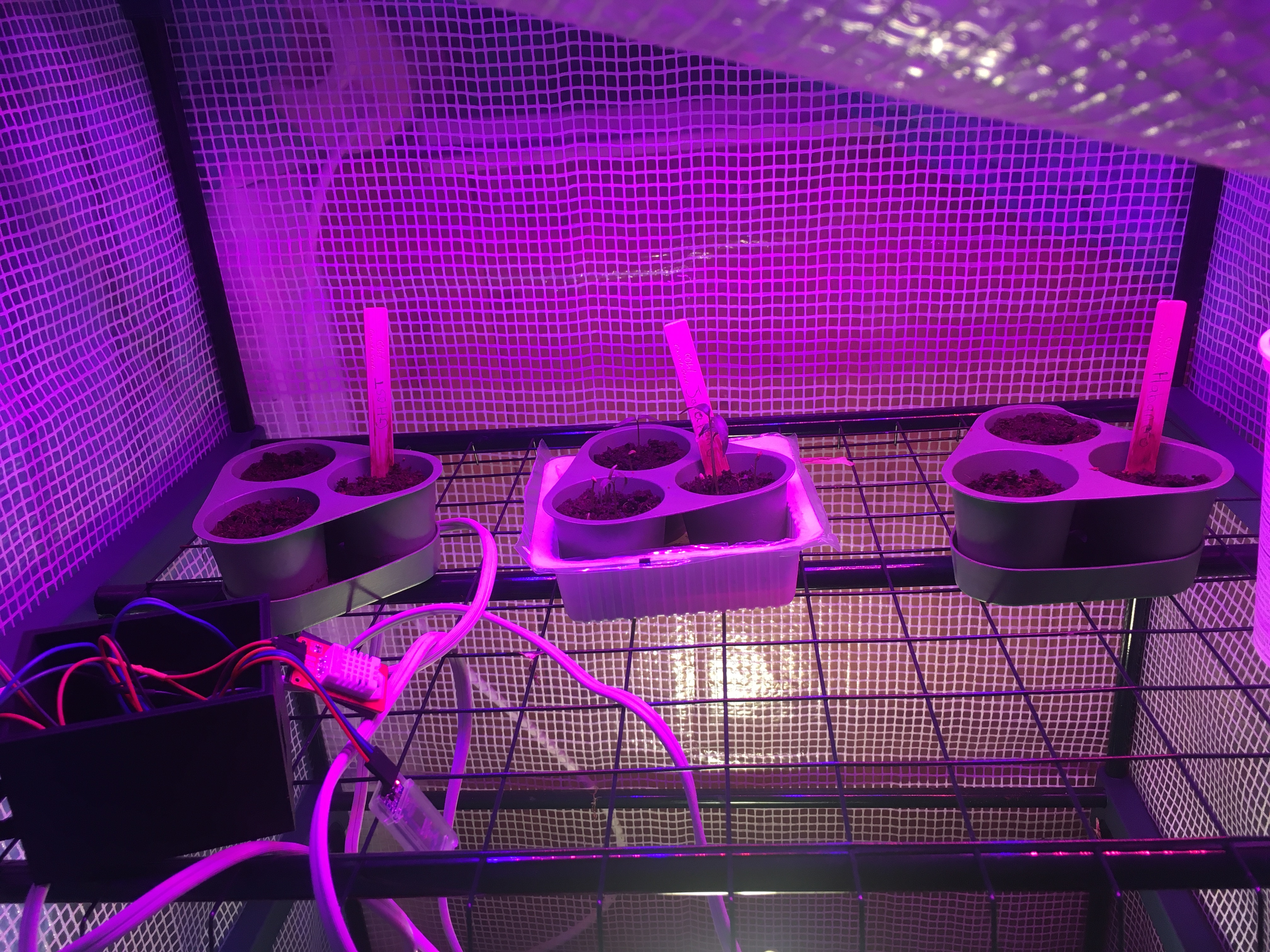
About a month before Christmas, I bought myself this hot pepper seed kit from Oh! Canada Seeds in Halifax, NS:
Saturday, January 28, 2023
Hot Pepper Grow-Op
Sunday, November 6, 2022
Pool Drain Test
As mentioned in the previous blog post, a test was planned to position an AMOS equipped with a conductivity sensor in the pond / stream in back of our house, in order to see if there was any noticeable change in conductivity in the water due to draining of the pool. The pool uses salt and a chlorinator during the summer months to keep it clean, but we need to drain it every fall before the water freezes, to make sure there isn't too much ice build-up in the winter. The water within the pool had a conductivity of 4.395 mS/cm.
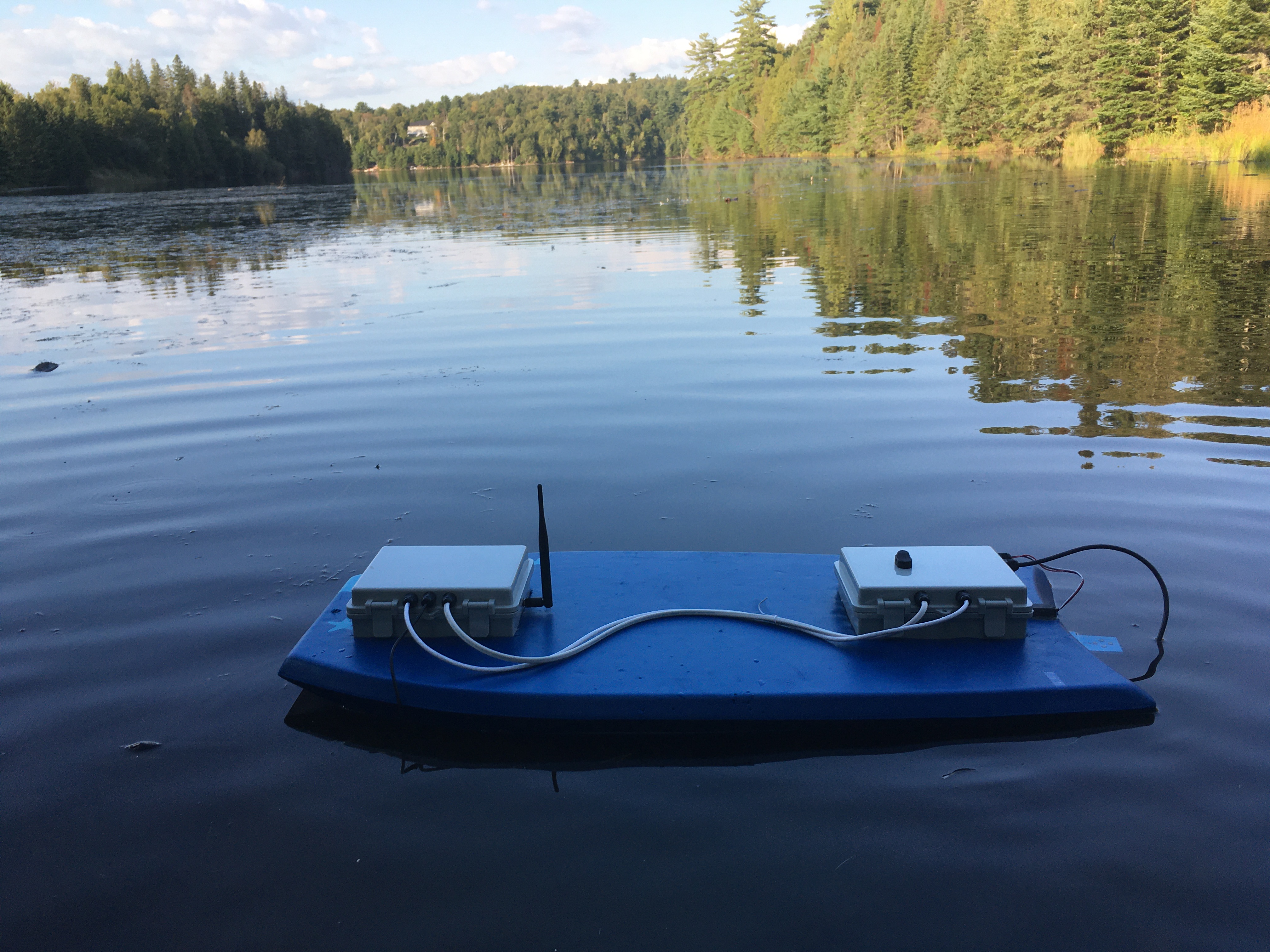
The location where AMOS was placed unfortunately had a fair amount of tree cover:
but thankfully not many leaves were left, and there was a nice bit of sun on the afternoon when the bloat was deployed and this picture was taken (October 23). The depth of the water in this area was almost up to the top of my rubber boots.Thursday, October 20, 2022
Zippy Mini-AMOS
Shortly after fixing the software issues for control of the upside-down servo motor on Mini-AMOS, an improved mechanical attachment was created for the servo, and the boat was brought back to Kelly's Creek for a new test. Only about an hour was available for the test, but the boat was able to travel down the river past a small island about 2 km away and back in less than an hour. The top speed was probably ~ 7 km/h, but with stops at checkpoints and pauses to periodically check the boat's heading, the average speed worked out to ~ 4 km/h. Probably some room for trade-offs there, i.e. sacrificing some positional accuracy for speed. Here's a short video of Mini-AMOS as it sped back past the island:
Monday, September 12, 2022
Mini AMOS / Wireless HAT Field Trial
It turned out that the output signal I was using to drive the relay switch on the Wireless HAT board was too weak: instead of activating the coil at 3.3 V, it got pulled all the way down to ~ 0.3 V. Fortunately the output wasn't damaged, and just needed a little boost. I knew I had purchased a bag of NPN power transistors about 4 years ago that never got used, but I searched all over the house, garage, and playhouse, to no avail. Probably they will turn up somewhere. Instead though, I discovered this old board:
Sunday, August 21, 2022
AMOS Wireless HAT version 2.0
The modified AMOS Wireless HAT boards arrived a couple of weeks ago, along with a larger A to D board for easier soldering, and a different 40-pin header that fits much more comfortably onto the Raspberry Pi board pins. I went ahead and populated all of the components, but did notice a few problems during assembly:
1) The relay switch is too big to fit on the top side of the board where it was supposed to go, and the package size for the switch is smaller than I expected, so it was necessary to solder some jumper wires onto the bottom side of the board to connect it.
2) The A to D board extends a bit too far over a terminal block that was intended for the A to D inputs. The input wires can just be soldered to the board directly though, so not a big problem.
3) The USB-serial converter board is dangerously close to the metal shell of the HDMI connector on the Pi board. For testing purposes, a piece of duct tape was stuck over the USB-serial converter board to avoid shorting. The USB-serial converter board is also directly over the camera connector on the Pi board, so there is no room to insert a camera cable. The HAT board needs to include a hole large enough to accommodate a camera cable.
4) A lot of the text that I had added to the second version of the board (company name, website, etc.) is missing from the board. I'm not sure why, but I'll try to figure it out before the next version.
Issues 2 and 3 could have been avoided with better 3D modeling I guess, but 1 and 4 require a board re-design anyway, so little would have been gained by fancy 3D analysis.
Here's what the top of the combined boards looks like when placed inside an electronics enclosure for testing:
You can't really see the wireless sub-module and and USB-serial converter because they are on the bottom side of the HAT board. Even though the compass module and GPS are not installed yet, and the wires from the battery box are not yet connected, it is clear that this should really reduce the amount of wiring, to clean up the enclosure.
This build will be a new shorter prototype AMOS with a single water prop. It won't be solar-powered, but I'm hopeful that it should be quick and speedy for relatively short (< 3 hours) missions. Here are a couple of pics:
Before flicking on the power switch to test it out, I checked for shorts on the 3.3 V and 5 V power lines. There were none, but I was still a bit doubtful that it would work, so I was pleasantly surprised to see the red power LED on the Pi board come on properly when I flipped the switch, and saw some reassuring flickers of the green activity LED also, indicating that the Pi board was busy with the task of booting up.
Initial tests of the A to D function, humidity / temperature sensor, and discovery / setup of the wireless module worked well, however the relay switch for going into sleep mode and the RTC module did not work. I'll need to debug these to figure out what the issues are. I'll also need to hook up the remaining components to test / debug them as well. Once it's ready it will be exciting to take it for a spin! 😊
Tuesday, July 26, 2022
Loose Fit, Tight Fit, and Misfit
This past month I was able to get AMOS out to the water a couple of times for some testing. The first time, I noticed that the boat always seemed to want to head off into the opposite direction. Initially I thought that the problem might have been an invalid initial GPS position, but even after physically moving the boat to other waypoints further along the planned track, it persisted in moving in a direction exactly opposite to the planned direction. Testing a couple of days later at home showed that the compass error was consistently about 180 degrees. I tried using an old compass calibration for the same device, but it too gave similar errors. I also double-checked the IMU board orientation within its enclosure, but it was correct. The only thing I can think of is that the polarity of the magnetometers must have been reversed somehow. Nothing in the part's datasheet says whether this is possible or not, and I'm not sure what sort of event (large magnetic field nearby?) might have caused the reversal to occur. During the last calibration, the heat got accidentally left on during the final temperature calibration, which caused some of the calibration apparatus to melt, and undoubtedly exposed the chip to some higher than normal temperatures. Perhaps higher than its specified limit of 85 degrees C. Not sure if that could have caused the polarity of the sensors to reverse though.
For AMOS's second trip to the water, the IMU board was simply reversed, so that it could properly be used for navigation. The fish finder was running, measuring depth, and an underwater Weatherbox was used to record some underwater videos at various points along the course. Here's a short video of AMOS setting out on the course:
and the resulting interpolated depth map that was produced:
However, the Weatherbox had a bit of a leak, and must have quickly filled up with water, because none of the videos recorded were recognizable (mostly weird brown color flashes and bits of electronic noise). Unfortunately, the Raspberry Pi camera died after about 2 hours (the last recorded video was cut short) and couldn't be revived, even after a thorough drying later at home. Initially I thought that the leak might have been caused by the parts coming loose due to the temperature difference of the water (colder) vs. the air (warmer) where the parts were screwed together. But a later test at home in a bucket of room temperature water showed that the screwed together parts leaked fairly rapidly, and a closer inspection showed that there were some imperfections in the glued surface under the o-ring. Repeating the test with a different WeatherBox showed no leaking at all after 24 hours. Re-gluing the original WeatherBox, using a 10 lb weight to hold down the o-ring helped reduce the amount of leaking, but did not get rid of it entirely. It's possible there could be some other crack or imperfection in this WeatherBox that is causing leaking to occur. I think I will need to fit the WeatherBox with a leak sensor or two to help save money on Raspberry Pi cameras. 😏
I started working on populating the AMOS Wireless HAT board last week. I started with the 40-pin female socket for plugging into the 40-pin male connector on the Raspberry Pi, since I had some uncertainty about the board design and how it would fit atop the Raspberry Pi board. I soldered the 40-pin female socket to the Wireless HAT board, and then went to try plugging it into the Raspberry Pi board, but realized that the socket was soldered to the wrong side of the HAT board. Oops. So I took out another board, and soldered a new connector to the proper side of it this time. But when I tried to plug it into the Raspberry Pi board, it didn't really want to fit. I could make it fit by using a very large pipe wrench, but large pipe wrenches and circuit boards don't mix well. And commercial HAT boards plug into the Raspberry Pi board quite nicely, without any use of excess force. So I ordered some (hopefully) better 40-pin connectors on Amazon, which claim to be designed for use with the Raspberry Pi. I then tried my hand at soldering the tiny AtoD chip to the board, to see whether that was possible. It was not. The heat / size of my soldering gun, and my general lack of soldering skill was too much for the tiny pads, and they were easily mutilated and destroyed. So I also ordered a few evaluation-type AtoD boards from Amazon which are much larger and easier to solder, and adjusted the PCB design accordingly. Hopefully all of the parts and modified boards will be here in a couple of weeks, so I can try again.
Monday, April 18, 2022
AMOS Wireless HAT Module
A lot has happened in the last few months, both in the greater world and in my own life. The war in Ukraine has unfortunately occupied much of my attention. I'm hopeful that the Russian invaders will be repelled from that country, but the present situation there is terrible, and I fear for the worst, both for Ukraine and the world as a whole. In my own life, I started officially working full-time at Measurand in March, although I had been unofficially working there full-time since November of last year. This means a bit less time for AMOS and In Nature Robotics, but the job itself is interesting, involving embedded product development and firmware. Plus having a full-time salary is helpful, given the way costs seem to be going higher and higher lately.
In my own experience using AMOS, and in some of the feedback I've gotten from customers, one recurring issue has been the tangle of wires within the AMOS CPU box that connect the Raspberry Pi to the rest of the equipment (wireless module, AtoD, sensors, etc.). Sometimes one or more of these wires become disconnected, and it can be a challenge to find the disconnected wire and attach it to the correct location.
Enter the new AMOS Wireless HAT (HAT stands for Hardware Attached on Top).
It has a 40-pin header that plugs directly into the Raspberry Pi board, and uses printed circuit board traces rather than wires to connect the AMOS wireless equipment, AtoD board, and temperature and humidity sensors. It also allows direct soldering in of wires from the battery box module (for the propeller and rudder control).
I have already noticed a few things that should be changed on the board, but the order for the first 5 prototypes is already in production, so I'll populate one to see how it goes, and then make some changes after that.
The weather here is warming up; I'll need to get the demo AMOS up and running again to do some weekend testing again soon!