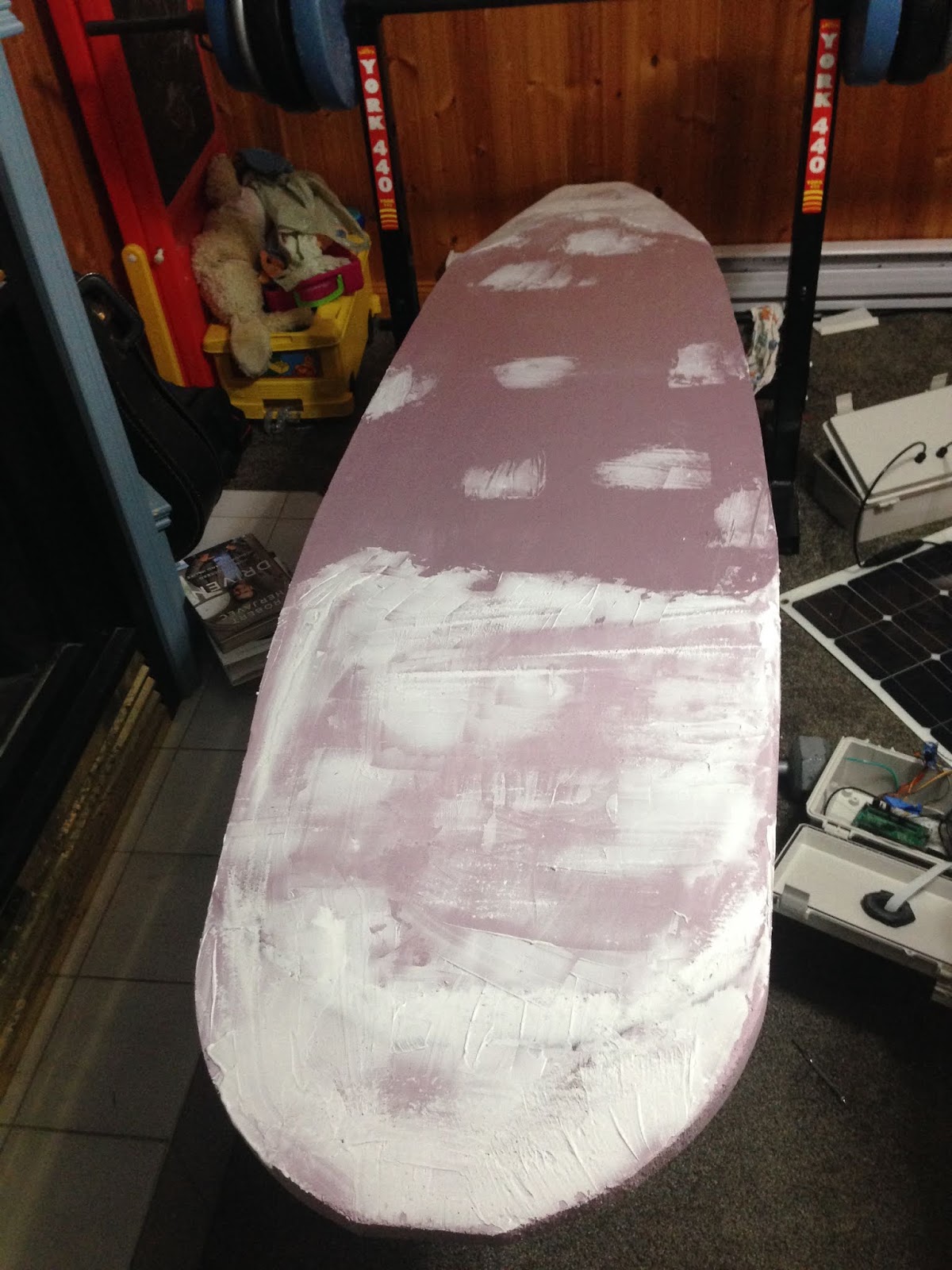
Merry Christmas! The fiberglass cloth and epoxy resin arrived this past week just in time for Christmas, so I figured that AMOS's new foam board should get a nice coat of fiberglass for Christmas, to protect it from getting any more dings or gouges.
First, I used a bit of polyfilla mixed with a few drops of water to fill in some of the pits and cracks that were mostly on the bottom of the board, then after waiting half a day or so for it to dry, sanded it down:
On Saturday I fiberglassed the bottom half of the board, using some painter's tape to hold the edges of the cloth to the perimeter of the top surface:
My technique was loosely base on a series of YouTube videos on fiberglassing foam surfboards. I wasn't really as careful as I should have been in making sure that the epoxy resin did not exceed the tape boundary. This didn't really hurt anything, but resulted in some of the tape getting permanently stuck to the board. I also wasn't particularly good at keeping ridges and bubbles from forming on the glassed surface. In hindsight, I probably should have been more careful to stretch and wrap the cloth prior to gluing.
Yesterday, I fiberglassed the top half. This part was slightly better, but I still had a number of ridges, especially around the edges of the board:
The important thing though, is that AMOS now has a nice protective coating, and I'm fairly confident that it should be able to withstand collisions with rocks, and be able to be strapped down to the roof of a vehicle without damage. This protection carries a bit of a price in terms of weight though, the weight of the board is now 10.2 lbs instead of the 6.5 lbs that it was initially before adding the coating.
Last week marked the first time that I have ever been interviewed about AMOS:
Kirsten had interviewed me for a French project that she was doing at school about courage. We initially tried to conduct the interview in French, but it did not go very well; too many pauses, poor word choices, and bad pronunciation. So thankfully Kelly was able to do a great voice-over that made it sound really professional!
This past week I spent a bit of time updating the Boat Captain software for iOS, so that it now has close to the same functionality that the PC and Android versions have. Then my waterproof containers and cable glands arrived, so it was time to tear down the old beer cooler AMOS and build up the new surf-board version. This involves a lot of cable labeling, de-soldering, re-soldering, etc. and it looks like I'm going to be at it for a while.
I allowed the glue to dry for three days under the pressure of my weights. The construction adhesive package recommended curing for 24 hours, but I thought it would be safer to give it some extra time. After that, I made some cuts at the front and back with a hand saw in hopes of improving the hydrodynamic shape:
I think the result was reasonable, given my lack of experience and skill in cutting this stuff. The hand saw did leave some rough looking divots in the foam though, which will require filling with a bit of pollyfilla or similar.
I have also ordered some fibreglass cloth and suitable epoxy which supposedly will not eat away at the foam for covering and protecting the boat surface. Right now the boat is nice and light (about 6 lbs) and the fibreglass will add some weight, but if it works it should be worth it I think in terms of the added protection and better look.
The current monitoring circuit that was begun last week was finished, and software was added for the PC and AMOS to view the amount of current that AMOS was consuming on its +12 V circuit. Also added to this diagnostics display was info on the leak sensor status, and (if a serial wireless link was used) the measured RF signal level in dBm. Here is a new screenshot of the BoatCaptain software for the PC (GPS position and time are incorrect because the boat was in the basement):
In an effort to make AMOS lighter and more hydrodynamic, some EPS pink foam insulation was purchased at Home Depot this weekend to make an inexpensive surfboard base (i.e. as a replacement for the trusty, but slow beer cooler). I had studied a number of online examples from people who had made their own paddleboards from this insulation material and had chosen this one in terms of its clear instructions and apparent usefulness (it seemed to actually work): https://www.instructables.com/id/Paddle-Board/
I printed out a picture of a suitably proportioned surfboard, figured out what the scaled dimensions should be, and then cut out a half-template from 1/4" plywood. This plywood was then used to draw both halves of the surfboard on two 2" thick insulation sheets:
The two halves were then glued together with two tubes of construction adhesive and my entire collection of weights were used to apply pressure. After a few days of drying I'll go around it with some sandpaper to smooth it out. Hannah is convinced that it will be too unstable and tippy, even with fins on the bottom and the weight of the electronics, motors, solar panel, and battery on top. Kelly figures it will probably break apart if I try to strap it to the roof of the van. (It can actually fit in the van, but doesn't leave much room for passengers.) So we will see. Perhaps if we get some warm weather and the pond next door melts I'll be able to try it out.
Work continued this week with the pair of RFU220 wireless transceivers. The software for AMOS and the PC are now working pretty seamlessly, so everything that could be done before with a WiFi or cell link can now be done with this serial wireless link. I also soldered up an extra pair of communication lines to the PC transceiver which lets me poll it for additional data, like for example the strength of the wireless connection. That should be useful as a troubleshooting tool when the boat becomes unresponsive and starts floating out to sea. 😉 To allow the link to work with an Android or iPhone device I think I would probably need to add some sort of a Bluetooth low energy dongle, to allow the phone to communicate with the serial transceiver.
Some long awaited spare propellers arrived today, so I replaced the warped and broken one with a new version; here is a comparison of old vs. new:
To evaluate whether or not there was any difference in thrust between the two propellers, I used my kayak straps to suspend AMOS from a beam in the garage, and measured the horizontal deflection distance at full throttle. There was no noticeable difference in thrust between the two, at full speed they both gave AMOS a horizontal deflection of ~ 1 inch. Based on the weight of AMOS (36 lbs) and the suspension distance (~ 4 ft) this translated into a pretty small thrust; no more than a pound. One added benefit of the new propeller though was that it ran much smoother, and there was no noticeable resonance at any speed whatsoever. So at least I was able to remove those lines of code that disallowed any speeds between 3 and 6. The lesson learned from this thrust test is that AMOS needs to go on a diet and slim down (i.e. become lighter and more hydrodynamic) if it actually hopes to use an air propeller for real navigation.
Right now I am soldering together some current sensing capability to the transceiver module on AMOS. I am basically just using the two ends of the ground return cable on the +12 V supply as a sort of shunt resistor and amplifying the voltage between the two ends with a surface mount op-amp that I had from an old project. The eventual goal is to add some software and enough smarts to be able to gauge how much battery power is left or how long it will take to charge given the amount of available sunlight.
Last Wednesday Kirsten and Bexie joined me in the AMOS development lab (i.e. our family basement) as part of "Bring Your Kid to Work Day". Their first task was to design and build a boat out of cardboard, glue, and duct tape, and see how "seaworthy" it was in our bathtub. Bexie opted for a surfboard type of design, which used only a couple of pieces of cardboard:
It was quite stable, moved well in the water, and was able to carry quite a few coins of "ballast". It definitely out-performed my boat which was not at all stable, and quickly filled with water and sank. Kirsten's boat was similarly stable, but was able to carry more coins due to its three dimensional construction and increased buoyancy. Here is a video that Kirsten took and edited. She opted to go all out on the video editing 😏:
The second task was to solder some wires from a wireless transceiver (the RFU220SU from Synapse (https://synapsewireless.com/resources/core-technology/)) to a USB-RS232 breakout board. Essentially the goal was to see if we could assemble our own wireless startup kit using $50 in parts rather than the $300 or so that it would cost for a commercial version. After taking two minutes to transfer all of my soldering "know-how" they got to it and did a great job. At first when we tried it out in the Synapse software, the wireless transceiver did not get detected, but I had read somewhere that there was a possibility that the RX / TX labels on the breakout board could be incorrectly assigned, so we tried reversing them and voila, it worked - the software detected the board, and we were able to see the various parameters associated with it.
For the third task, I showed them some sections of code in the Android "Boat Captain" software that I wanted to change over to allow it to specify a rudder angle and propeller speed instead of the left and right propeller speeds that the previous version of AMOS required. They did a great job on this also.
The rest of the week was not as fun without my co-workers, but I did manage to get a pair of the Synapse wireless transceivers working, sending data back and forth between my PC and AMOS at 115200 bps. I also modified the main AMOS software to be able to use this wireless serial link and started modifying the PC version of the "Boat Captain" software to do the same. At some point I would like to do a "range test" of these transceivers to see if they can really get anywhere close to the three mile line of sight range that their spec sheet claims. These transceivers also have a lot of extra processing and I/O capabilities beyond basic communications, eg: A to D inputs, digital I/O, PWM outputs, etc. so the one connected to AMOS could be used for measuring voltages, currents, and even acting as a sort of hardware "watchdog" for AMOS to make sure that it is still functioning correctly. If not, it could execute a hard reboot of the Pi board to get it up and running again.
I didn't get to Woolastook for any field tests last week, but was still able to learn plenty from some simple tests in the pool before its surface froze over a couple of days ago. The first obvious problem was that the cage / support for the propeller, including the air rudders tended to resonate (quite a bit actually) over a certain range of propeller speeds. The electronic speed controller for the propeller uses pulse width modulation to control the speed, and in my software I have assigned an arbitrary scale of 0 (minimum speed) to 10 (maximum speed). The resonating vibrations begin at a speed of about 3, reach a maximum at around 4.5, and then taper off over 6, completely disappearing at 7. The shaking was so bad at around 4 or 5 that the tip of the propeller collided with something and broke off. I think probably that the cage should be made from aluminum wires or similar, something sturdier than PLA. So I modified the software to just avoid all speeds between 3 and 6 and that took care of the resonance issue.
Additional pool testing showed that the directional control of the boat using the air rudder was a bit swervy. Partly this might be because there is less of a turning moment (with the air rudders) than the boat had before when it could change the thrusts of the water propellers mounted on the left and right (er port and starboard) sides of the boat. But testing out the compass module output in the software, I noticed that there was more noise in the compass heading data when power was applied to the air propeller. More power = more magnetic noise. The cables supplying power to the air propeller were a few inches away from the magnetometer, but they were close enough to cause random fluctuations of a few degrees, which didn't help with maintaining directional control.
So I did a bit more work on the inertial measurement unit (IMU) that I had picked up a few weeks ago, and finished a new software class for it and just today finished integrating it into AMOS's main program. Just turning the circuit board by hand, you can see that the output orientation angles that it provides are nice and smooth; much better than what was obtained with the compass module output. Magnetic interference from powering the air propeller will still be a minor issue for steady-state magnetic heading measurements, but for real-time control of the boat's direction, the gyros should do a very nice job of measuring the dynamic orientation of the boat, allowing the air rudder control software to maintain a steadier course.
Tomorrow is "Bring Your Kid to Work Day" and Bexie and Kirsten will be joining me in the morning to help work on AMOS. One of the things that needs to be decided upon for the next revision is the shape / design of the hull. So we will be building some toy-sized boats out of cardboard and duct tape and testing them out in the bathtub to see how stable and seaworthy they are. Here is the example boat that I made:
I have no doubt that the girls will be able to do much better!