Work on AMOS took a brief pause for Christmas, but has continued on during this final week of 2020. On Monday, I had wanted to do another test of the RTK / GPS equipment using a laptop hooked up to the base station equipment (in the playhouse) and a second laptop hooked up to the remote "rover" equipment, that was moved around the backyard. This was similar to the previous test done last week, except a laptop replaced AMOS as the rover. Using a laptop running Windows allowed me to run the Windows diagnostic software that came with the equipment, to see what mode the rover was in ("acquiring 3D position fix", "RTK float mode" or "RTK fix mode"). The latter of these modes provides the best position accuracy and precision, down to cm-level. The weather that day was a bit rainy and snowy, which required the use of this handy recycling box / makeshift laptop shelter:
Wednesday, December 30, 2020
Holiday AMOS Work
Tuesday, December 22, 2020
New AMOS Board
(EDIT, Jan. 07, 2021: For more info on AMOS and In Nature Robotics, please also visit https://www.innaturerobotics.com/)
It pained me somewhat to carve up a brand new surfboard fresh out of the box, but I used the two AMOS electronics boxes as guides to carve out rectangular holes in the bow and stern and then wedged the boxes in. The fit was pretty snug, so I didn't bother gluing anything down:
This last video showed a bit of a problem that the compass was having with giving accurate heading when the boat should have been moving south. The compass error must have been pointed towards the southeast, because the boat would start in that direction, realize that the new target direction was southwest (or even west) to get to the next waypoint, and then move in a big curve to correct for the initial path error. The temperature in the electronics box started off at 8 degrees C at the start of the test, and fell to 3 degrees C by the end. The magnetometer calibration was done at -3 degrees C, so that might have been a source of error. And probably there was some error from the Z-axis (vertical) magnetometer on the compass, since it had never been calibrated on this unit, and the new inclined angle of the bow on this boat would have caused that magnetometer to come more into play for determining heading.
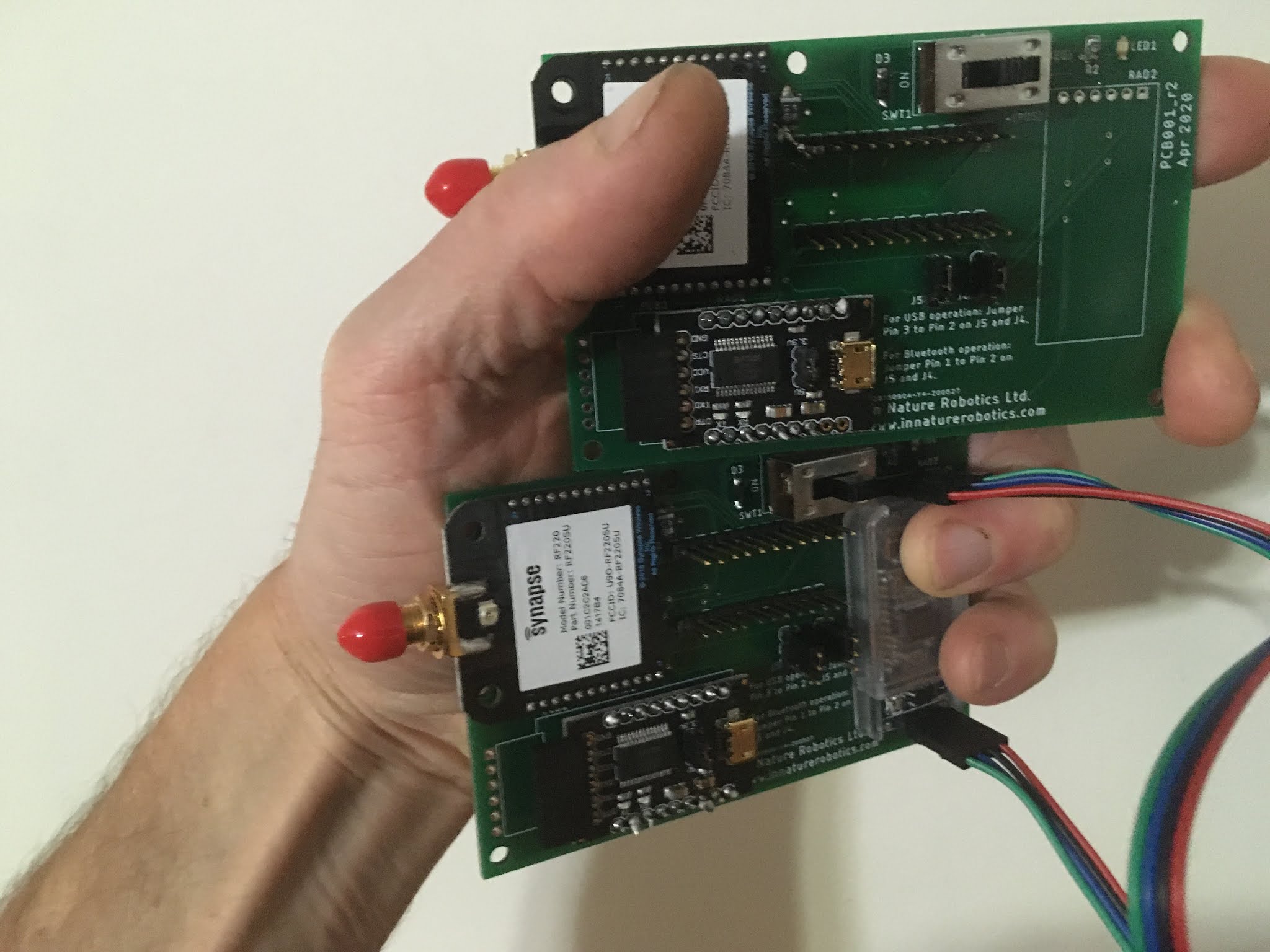
Thursday, December 17, 2020
Testing Out New Gear
Since the test with the new motor described in last week's blog ended abruptly with a tree collision, I went back the following day to try again, this time with a better "cold-temperature" magnetometer calibration. I also launched the boat from the kayak, just beyond the trees as a precaution. There was a light wind, a fair bit of current, and the sun was out providing a bit of warmth. It was almost possible to forget that it was the middle of December.
The new motor did great - going against the current I believe it was a lot faster than the old motor would have been:
I ordered a 6 foot kids surfboard:
a feel for the accuracy / precision without using the RTK base unit, I put the rover unit on AMOS and carried it around the perimeter of our fence, about 1 foot inside the fence:
Thursday, December 10, 2020
New Build With New Motor
Much of the past few weeks have been spent assembling the electronics boxes for the next AMOS version. The LiDAR module just arrived yesterday, so it is not on yet, but pretty much all the other electronics are assembled, including a new motor.
Both boxes combined, and including the 10AH battery weigh only about 3.5 kg. In a pretty crude test involving a kitchen scale and the propulsion / battery box positioned with its back end on the scale, I was able to compare the lifting force of the two propellers for approximately the same input voltage, and the same 10" propeller. The new motor completely outstripped the old one, producing 2.5 times more lift for approximately the same input power, i.e. about 1300 g of force vs. about 500 g. Excited with these results, I strapped the electronics boxes onto the old AMOS surfboard:
And took it down to the river this morning for a test:I don't remember temperature having as profound an effect on the previous AMOS boats, but then again I only did a limited amount of testing at negative temperatures. So to be ready for the next test (assuming it will be somewhat close to -3 deg C), I re-did the circle calibration in the backyard (the original calibration was done at room temperature). It wouldn't be hard to have the boat do its own magnetometer calibration in the water. But better would be to calibrate and model the offset and possibly gain fluctuations of the AMOS-IMU sensors with temperature.
Tuesday, December 1, 2020
Building AMOS 4.0
The past couple of weeks have been spent putting stuff together for the next version of AMOS. It's going to be faster, more powerful, have a longer range, more accurate navigation, and it's going to look amazing. Some potential designs for the hull have been considered:
although nothing definite has been decided yet. Steven Fox, a mechanical engineering technician at Measurand has agreed to help me out with the hull design and construction in his off-hours, so no doubt he will greatly improve upon whatever I would have come up with. I had looked a little bit into 3D-printing or urethane casting for the next version, but these alternatives seemed quite pricey, and I wasn't sure how sturdy the finished product would be. So for now at least, it's looking like it is going to be another foam and fiberglass construction. Just better looking. 😎
Prior to this build I watched a couple of how-to soldering videos on YouTube to refine my technique, and then put together a couple of AMOSRemote boards, one for the handheld unit and one for AMOS:
Tuesday, November 17, 2020
Breaking the mold
This weekend I tried out a plywood mold and two-part foam for building AMOS hulls. Everything went well for a while: I had the shed / playhouse heated at the right temperature (about 25 deg C), and got 5 or 6 batches of the foam properly mixed and poured into the mold. The foam expanded similar to what I had seen on the Internet beforehand, and there seemed to be a sufficient number of vent holes to relieve pressure from the expanding foam. Then I tried to take the mold apart. The interior had been lined with plastic wrap, in order to prevent the foam from sticking to the wood. Except it didn't work. The foam somehow tended to get underneath the wrap, and in some cases seemed to melt it and mix with it. I tried to hack and cut away at the wooden exterior of the mold, but only succeeded in breaking everything, including the foam pontoons. Here are some pics of the carnage:
Tuesday, November 10, 2020
The Cape Breton Tour
Later that day Lawrence and I drove to Whycocomagh in Cape Breton where we had rented a cottage on the shore of the Bras d'Or Lake. Here was our view from the front porch the next morning:
After the demo, Lawrence and I went out with Bruce and Allison and Piotr to check out a 50 m "Death Hole" with a couple of ROVs. This hole featured a mysterious layer of floating material about 16 m deep that both ROVs were able to examine with their camera systems. Allison and Piotr's ROV collected water samples for their lab at Dalhousie University using a very cool apparatus of spring actuated syringes. Bruce's ROV collected a smelly, dark sample of mud from the bottom of the hole:
On the return trip back to Dartmouth, Lawrence and I stopped near Antigonish to try collecting some data in Pomquet Cove. The wind here proved to be a bit too much for AMOS, so we tried a stream on the other side of the highway instead:
The water in the stream was a bit mucky and shallow in some areas, and required a few minutes of manually controlling AMOS to get it unstuck and drive it back to a location where it could be easily retrieved.
- More power, need a larger propeller, larger motor, and larger / more batteries.
- More streamlined and durable construction.
- More accurate positioning (i.e. requires a GNSS system).
- Need to have ability to reverse direction of propeller for backing out of tight spots.
- Software improvements for defining survey grids, saving / loading standard GPS coordinate file formats.
Thursday, October 29, 2020
An Interruption Most Rude
On Tuesday evening I was speaking about AMOS (over Zoom) to the Raspberry Pint group in London, England. It was supposed to be an update of the last 9 months of development work since I had presented to them previously back in January. I started off with a recap of the reason and history behind AMOS, and then got into the details of the recent improvements on the AMOSRemote wireless transceiver, the AMOS-IMU electronic compass, and then... my screen turned red. Entirely red. I was able to press the ESC key to view windows in the background, but the PowerPoint was still red. We decided that I should try to stop sharing, and then try re-sharing to get it going again. I clicked the 'Stop Share' button, and that's when the stream of porn and loud music started. The presentation had apparently been hacked by someone. A couple of the guys tried some things to resume control with unsatisfactory results, but then had a pretty clever idea: ask everyone to turn on their video. Anyone who didn't comply would be booted out of the presentation. I think this resulted in a few people needing to leave who didn't have working cameras, but the intruder must have also left, because I was free to continue my presentation after that. The "intermission" had been about 10 minutes, and I felt a bit weird for a few minutes after that, but I was able to finish without incident and answer the questions from the audience afterward. Hopefully it will be possible to splice together a video of my presentation at some point. Until then y (Edit: Richard Kirby at Raspberry Pint has already edited the video: https://www.youtube.com/watch?v=yHVf25cZ-AI&fbclid=IwAR2EUiuZ1--wo5dYfUvKESNI-UL03GPUu0JSVwXt4maH_EfZ_fMTm4NZLsI )You can see the PPT slides here (guaranteed to be family friendly!):
https://drive.google.com/drive/u/0/folders/12L3EXMMcrxIQD2Ic7eXweo_RAyHzjQuS
This week has been fairly busy with meetings, but there has been a bit of time to work on the creation of a mold for constructing AMOS hulls out of two-part foam:
Wednesday, October 21, 2020
Towing The Line
Someone interested in AMOS recently inquired if it would be possible for it to tow a similar sized (~ 10 kg) boat behind it from one side of a river to the other and back without deviating downstream from the intended path. I responded that it should be possible if the speed of the river were not too great, i.e. too close to (or beyond) the maximum possible speed of AMOS in still water and wind, and that I would attempt a test using the old AMOS surfboard prototype as the vehicle to be towed.
On Saturday we had a lot of rain (I think around 30 mm) and I didn't want to get wet, so I waited until the following day to do the test. On Sunday it was nice and sunny so I took AMOS down to the river and attached the surfboard base from prototype #2 to the back end and duct-taped a 5 kg weight to the top of the surfboard to simulate a10 kg boat:
Because of the recent rain, the river was very fast. Near the west shore (where AMOS started) it appeared to be ~ 0.5 m/s at the surface, and out in the middle it was more than that (~ 1.1 m/s, see drift calculation below). For some reason, the flow was a bit less on the eastern shore, but probably still ~ 0.3 m/s or so. The photo below shows the intended crossing in yellow, and the actual path in white. On the first attempted crossing from west to east, the battery charge was detected as low (I have been having some problems with the LiFePO4 battery maintaining its charge recently, I think because it has been close to 0 deg C here) so AMOS shut itself down and drifted about 400 m downriver without power for 6 minutes. This would correspond to a surface flow speed of about 400 / 360 = 1.1 m/s, or about 4 km/h, which is too fast for AMOS, especially when trying to tow a second boat. I towed AMOS and the surfboard in my kayak over to the eastern shore, and then let it try to go back west on its own. It was relatively close to the intended course (within 30 m) for about 250 m of westward travel this time, but then the strong current in the middle started to get the better of it, and once again the battery charge got low, so I shut it down and towed it back to the start.
Some videos of the test were recorded here:
https://drive.google.com/drive/u/0/folders/1yRDRWJ9n-_gsIMj5ravp85tAzXxHyVYP
Probably using some water flow velocity sensors would help to keep the boat closer to the intended line, assuming the maximum flow velocity were not too great, but the navigation algorithm would still need to rely on GPS on top of this to make sure that the intended course was being followed. The GPS used in AMOS is a low-cost model, and has a typical accuracy of something like +/- 10 m. High quality handheld units can get down to a couple of meters accuracy I think, and if you want cm-level accuracy you need to use surveyor-type hardware. I'm not sure about the technical feasibility of putting surveyor-type hardware on a robot boat though.
At any rate, I'm going to re-attempt the straight-line test without the tow vehicle either tomorrow or the following day. The electronic speed controller will be moved back into the battery box for this test, in order to provide a bit of warming for the battery enclosure. It had been moved outside the box, behind the propeller this summer to prevent overheating in the hot summer sun, but that isn't really an issue now near the end of October.
Next week I will be presenting an update on AMOS to the Raspberry Pint group via Zoom: https://www.eventbrite.com/e/raspberry-pintdigital-making-fun-with-raspberry-piarduino-esp32-etc-tickets-124921590841?utm-medium=discovery&utm-campaign=social&utm-content=attendeeshare&aff=estw&utm-source=tw&utm-term=listing @Eventbrite This is a very tech-savvy group, so will be a good opportunity to get some feedback and tips!
Wednesday, October 14, 2020
I2C Wiring Update
AMOS was taken out for testing a couple of times this week, but unfortunately there were issues with its performance. It would startup and spin around in a circle, without getting any valid data from the electronic compass. After re-powering, it would cease to work altogether. Some of the re-wiring that I had done the week before to clean things up and get more stable power levels had mistakenly wired the pullup resistors on the A to D converter to +5 V instead of the +3.3 V level that the Raspberry Pi 3B+ computer uses for its logic signals. Also, the compass and realtime clock module were both being powered by the +5V supply line, when in fact they should have been powered by the +3.3 V supply, since the pullup resistors that they have wired directly on their circuit boards were connected directly to the input voltage pins of their respective circuit boards.
Even with the I2C pullups wired to the wrong power supply voltage, it still worked. Or rather, it worked when the propeller was not being used. If the propeller speed was ramped up very quickly, the compass module would often fail catastrophically, requiring nothing less than a full system shutdown and powerup to get it working again. Probably the Pi could usually sink the required amount of current to keep the I2C clock and data lines at the right logic levels, but the added system noise that resulted from quickly turning the propeller to full speed must have created some issues. The initial thinking had been that there was too much noise in the +5 V supply for the I2C devices to function correctly, so I moved the DC-DC converter for generating this voltage closer to the Pi and added a large capacitor (1 mF) between +5 V and GND. It didn't help. After a number of tests, experiments, and hours spent searching the Internet, it slowly dawned on me that the devices should be wired in to the +3.3 V supply instead of the +5 V supply. The one exception to this is the LiDAR module, which still uses +5 V for its power supply, but (when needed) its documentation recommends installing pullup resistors to the logic level voltage, which in this case would be +3.3 V. Because there are already 4 devices with pullups on the same I2C bus though, no pullups for the LiDAR module were required.
Once everything was correctly wired up to +3.3 V it worked great! I was able to ramp the propeller speed quickly up and down without any catastrophic issues. Occasionally a compass data sample would timeout or be missed, but the device always recovered and kept working without needing to reset things.
A second significant fix was made this week for backing up and restoring the configuration file that AMOS uses. Sometimes if a user switches off power to the boat while the software is writing to this configuration file, it corrupts the file, leaving it as a zero byte file. This would cause AMOS to crash the next time that it booted up. The solution was to backup the configuration file every time on powerup that it is read successfully, and resort to this backup in the event that the original file gets corrupted. Initial tests seem to indicate that this system works.
I am looking forward to building the next prototype version of AMOS. Most of the parts for it have been ordered, and I'll pick up some insulation foam sheets from the local hardware store to construct and shape the hull. This time around, I would like to build the hull shape from the glued together insulation sheets, as before, but then use that shape to make a silicone mold for quickly making additional shapes. The additional shapes could be made with a two-part foam mixture, which would cure in the silicone mold and could allow for electronics boxes to be easily inserted into the hull structure while the mixture is curing.
Tuesday, October 6, 2020
Check the Spam
I have what might be called an on-again / off-again relationship with my spam folder. Some weeks things are a bit slow and I'll browse it for some cheap amusement to find out what lucrative business opportunities I'm missing, or what strange perversions against human decency I am being blackmailed for. Other times I'll go for weeks without checking it, only to find out that there was actually a valid email in there needing my response. This evening I discovered 3 emails from 8 to 12 days ago requesting my approval and confirmation to be part of a virtual maker fair in Shanghai China, that I had applied to shortly before that (http://www.makercarnival.org/). I did respond to them this evening, so hopefully that will be enough time before the fair starts on October 14.
This week turned out to be a bit discouraging in terms of development work. I had been trying to 3-D print an enclosure for this solenoid valve:
which could house a "dry" compartment for electronics, while maintaining a separate enclosure for a water sample of about 200 ml. So far, no combination of solenoid valve, 3-D printed enclosure and other parts and o-rings has been sufficient to keep water out of the dry compartment. And no we're not talking about 100 m of water pressure or anything. We're talking about leaking under kitchen sink pressure conditions. Granted it is a pretty slow leak, but still. I was hoping for better. Some sort of new approach is required for this I think.
On Saturday I took AMOS out to Kelly's Creek for what I hoped would be a long test and leisurely paddle. Nope. A wire got snagged on a stump right at the start and then AMOS made the beeping noise that it makes whenever it reboots. Only it hadn't rebooted properly, and I couldn't get it to startup at all after that. After taking it home and examining it, I was able to fix a wire that had come loose in the battery box. The following day I brought AMOS back to the same spot, but this time it weaved back and forth in a strange manner, as though the compass was not properly calibrated:
The next day I tested the compass out and it seemed fine, but today when I was running the propeller in the backyard, I happened to notice that I was getting a bunch of I2C errors on everything (including the compass) whenever the propeller was run at high speed. The battery box is now a terrible mess of wires and neglect and I really need to clean it up before I can begin to guess at what might be wrong. I was able to nervously open the box with the propeller spinning at max speed and measure the +5 V supply and it seemed OK, but possibly there is a transient problem with the supply when the propeller goes to max speed. Because the I2C problems persist even after the propeller has been stopped.
Always something to work on!
Wednesday, September 30, 2020
Ocean Startup Challenge Win!
The pitch in the Ocean Startup Challenge seemed to go OK last week, and fortunately the judges did not ask any really difficult questions. I wasn't expecting to be one of the top 10 companies, but was still kind of eager to find out the results. On Monday evening my phone rang while I was driving into town to pickup Kirsten from cross country practice. I pulled over and took the call, and was quite excited to find out that In Nature Robotics was one of the winners! As I found out just today when the official announcement was made, there were actually 14 winners chosen, so probably good for me that they decided to pick 40% extra! For a video and list of the winners, check out this link: https://www.oceanstartupchallenge.ca/announcements/. I also did a telephone interview with a fisheries / ocean tech journalist who writes for https://www.saltwire.com/, so there should be a story about me, In Nature Robotics, and AMOS appearing there soon. (EDIT: Here is the link to the story: https://www.saltwire.com/business/local-business/video-cod-collagen-project-and-a-boat-called-amos-east-coast-entrepreneurs-among-winners-of-ocean-startup-challenge-504940/)
The funding from the contest will be used to build a 4th prototype version of AMOS that will be a hybrid between the previous catamaran and surfboard versions. This time I would like to first make a silicone mold and then try using a two-part foam with that. I would also like to construct it so that the electronics boxes are mostly hidden away within the hull, in order to cut down on wind resistance as much as possible, and make things look a bit neater. I would also like to get some other people using and testing AMOS, to get their feedback and criticisms, and last I'm hoping to do a bit of R&D to work on adding some tech for discrete sample collection and underwater video.
I'll find out more details about the Ocean Startup program and funding next week. In the mean time I'm working on creating a 3D-printed container to house a small solenoid valve. It would be used for collecting physical water samples at different depths. I would like to fit a BLE (Bluetooth Low Energy) module, some batteries, and a microcontroller in there to allow AMOS to communicate with it wirelessly and tell it to open its inlet valve after a certain length of time. Then AMOS could lower the bottle into the water on a rope to the required depth and wait for the valve to open for a few seconds before pulling the bottle up again. A fancier version might also include a pressure sensor to allow the valve to open at a pre-determined depth.
Tuesday, September 22, 2020
Foggy False Obstacles
This past week has been mostly filled with preparations for my upcoming pitch in the Ocean Startup Challenge this Thursday (the 24th), but I did find a bit of time to get out for a quick test on Monday morning. The air temperature was quite cold that morning (a low of 0 °C the night before) so there was a lot of fog on the water when AMOS was starting out:
Similar to what happened a couple of years ago on a foggy day (although with a different LiDAR model) AMOS was detecting a number of false obstacles due to the laser light from the LiDAR reflecting back from the water vapour. AMOS would turn in place until it found a "fog-free" direction and then proceed for a while before changing direction again. This slowed things down a bit at first, but soon the sun burned the fog away and AMOS sped from one end of Kelly's Creek to the other, a distance of almost 6 km in about 80 minutes:
I had to work pretty hard to tow AMOS back to the van in order to get back home in time for lunch and work at Measurand.
My slides and presentation are ready for the pitch on Thursday, although I'm meeting with some people tomorrow to get their feedback, so they might still need a bit more modification. Anyone who is interested can view the slides and speaking notes here:
https://drive.google.com/drive/u/0/folders/1NDSK35QObOzhbu_-wzTQwxbSCig7iita
Tuesday, September 15, 2020
More Capacitors = More Speed
Work this week continued on efforts to re-wire the electronic speed controller (ESC) behind the propeller motor. This took way longer than I had planned, and involved swapping out the motor, swapping out the electronic speed controller, re-soldering all of the connections, re-calibrating the ESC, learning what all the ESC beeps meant and modifying the calibration software to be able to adjust all of the parameters according to those beeps. No matter what I tried though, the motor was always very choppy when run at medium to high speed. With nothing left to try, I resorted to Google, which fortunately came up with this web site that had a good discussion about some of the problems that can result with an ESC if your cables delivering DC power from the battery are too long: https://www.rcgroups.com/forums/showthread.php?952523-too-long-battery-wires-will-kill-ESC-over-time-precautions-solutions-workarounds
By positioning the ESC outside the box and behind the propeller, I had lengthened the cables delivering the 12 VDC power to the ESC by about a foot or so. The problem is not the extra bit of resistance that this adds, but rather the extra inductance that it adds. The inductance results in voltage spikes at the ESC, which can apparently result in erratic performance of the motor. The solution is to add extra capacitance at the ESC to help smooth out the voltage fluctuations. There is already a 30V 220 μF capacitor on the ESC, but the rule of thumb specified in the above website is to add an additional 220 μF capacitor for each additional 10 cm of power wire length. I added three 330 μF capacitors in parallel over the voltage inputs to the ESC. They were only rated for 25 V, but they seemed to improve things quite a bit, and were able to allow the motor to run at a normal speed. I also tried adding an additional 330 μF capacitor to see if it might allow the speed to increase further, and it did a little bit, although not quite as much as I had hoped.
So now there is an ugly cluster of capacitors and an ESC mounted behind the propeller. These would need to be weatherproofed with some silicone or other material if used outdoors on a consistent basis. Better positioning of the solar charge controller would also allow me to shorten the wire leads that power the ESC. Really the only reason for positioning the ESC behind the propeller is to keep it cool. Having it inside the electronics enclosure risks having it heat up to 110 °C on hot days, at which point the ESC firmware immediately cuts its output power by 50%. This sort of thing was happening occasionally back in August when the weather was sunny and the outdoor temperature was close to 30 °C.
On the weekend I took AMOS and its new capacitors downtown for a test run, and was happy that it beat its old record for going up and down the downtown section of river by 5 minutes: from 47 minutes to 42 minutes. The dissolved O2 levels were good too - I guess those are going back up again now that the water is cooling again:
Tuesday, September 8, 2020
Ocean Startup Challenge!
There was a big announcement today for In Nature Robotics: we were one of 31 companies out of 158 applicants to be picked for the next round of the Ocean Startup Challenge: http://www.oceanstartupchallenge.ca/announcements/. Starting this Friday, there will be a week of presentations and workshops to get ready for a final pitch presentation, sometime between September 22 and September 24. The 31 companies will be competing for 10 prizes of $25k plus in-kind support. It seems sort of similar to what we went through back in May for the Volta competition; except more of an overall ocean theme.
I took a couple of days off from AMOS this week to go on a fun family camping trip at Spednic Lake. It would have been nice to try out AMOS there, but the van was packed tightly to the roof with camping supplies, so it wasn't possible. I did manage to get some 3D models of the new WeatherBox put together and tested for water-tightness though. Here is a picture of the component parts (no more little nuts or bolts required!!!) and a picture of the put-together unit (minus the interior locking piece):
The only thing that needs to be modified is that the camera board is recessed a bit too far inside the enclosure, so that you can see tiny smudges of black (from the enclosure) in the corners of the field of view:
To fix this, I can try to either (i) elevate the level of the camera board inside the enclosure, or (ii) trim down the thickness of the enclosure a bit.
I have also been working on re-wiring the electronic speed controller (ESC) to situate it behind the propeller. Unfortunately though, I think I may have broken one or more of the wires going into either the ESC or the propeller motor today, as it was functioning sporadically, depending on how I moved the wire around. I'll try a replacement motor tomorrow, and if that doesn't work I'll try replacing the ESC.
Tuesday, September 1, 2020
Back From The Wilderness
Avid readers of the blog may have noticed that there was no entry last week; that was the first time in over 2.5 years that the weekly update was missed! Without going into too many details, a long 15 hour bike ride through New Brunswick trails and back roads turned into an even longer 24+ bike ride due to some navigation errors that resulted from poor preparation (forgot 1 phone charger and the other 2 chargers that were brought were not charged, did not bring a printed map (only printed directions), and did not bring proper equipment to change a bike tire, which turned out to be necessary for the last 50 km or so). After being rescued and returned to safety, I was in no condition to think about the blog, and thereby felt justified in skipping a week to catch up on some sleep. Many thanks to Kelly and Dad for searching for us and rescuing us after this misadventure.
The last time I had AMOS out for a test run was on August 22 at Kelly's Creek. One thing I happened to notice around the middle of this test was that the air propeller motor would sometimes audibly switch down to a lower speed, resulting in a somewhat lesser thrust. Going with the wind the reduction in thrust was not an issue, but on the return trip it was. Some testing in the backyard the next day revealed that the electronic speed controller (ESC) board output power became significantly less when it overheated. Currently, the ESC is sitting in the bottom of the back electronics enclosure, with the battery and a bunch of other electronics, so it makes sense that it could get pretty hot, especially if the weather outside is sunny and warm. By positioning the ESC outside the box, behind the propeller in the airflow however, the output power remained stable, presumably because the ESC was sufficiently cooled. Apparently drone makers know this already; there are instructions available on the Internet for applying a silicone conformal coating to the ESC board to protect it against moisture. The weather is starting to get cooler here, so I might not notice the overheating effect in future tests, but I think I'll re-wire things to put the board outside behind the propeller anyway.
Efforts are currently underway to re-design the WeatherBox (i.e. the waterproof enclosure for the camera on AMOS). I would like to get rid of the nuts and bolts and just have a window cap that screws directly onto the enclosure. This would make assembly a whole lot easier, and should look better too. Here are 3D printed versions of the base enclosure piece and an initial window cap (without the plexiglass window) screwed together:
This past week was Jata's last as an intern at In Nature Robotics. One of her projects was an online 3D modeling / ordering tool for AMOS. I have been trying to teach myself 3D modeling using TinkerCAD and other 3D tools to continue her work, but so far have not had much luck. Importing and exporting with these tools tends to do unexpected things to the models. Possibly it is just user error though!
Tuesday, August 18, 2020
Read The Fine Manual
Last Wednesday I was able to confirm by looking at the end of the dissolved O2 probe with a magnifying glass that there was a small crease in the membrane that was allowing air and water to leak in and electrolyte to leak out. So that confirmed why the previous readings had been getting progressively worse. Here is some better data collected at Woolastook with more electrolyte added and a new membrane over the end of the probe:
As you can see in the above screenshot, this time AMOS followed a route through the middle of the water, where it was relatively deep and there was little danger of damaging the end of the probe by dragging it against rocks, sticks, or other objects. The following graphs show the dissolved O2 data collected so far out at Kelly's Creek and near downtown Fredericton:
The results recorded in early August should be ignored, as the probe was most likely leaking at that time.
We entered an application in to the Ocean Startup Challenge last week: https://www.oceanstartupchallenge.ca/. I know of at least a few other people that have also entered submissions, so probably this contest was quite popular. On September 04, we will know whether or not our application made the short list.
Just this evening I finished a 6-page quick start manual for getting up and running with AMOS. It hasn't been tested on anyone yet, although Kirsten volunteered to try it out and see if she could get it to work, so I'll try to take her up on that. Check out our support page: https://www.innaturerobotics.com/support to have a look. RTFM! 😀
Tuesday, August 11, 2020
Leaky Dissolved O2 Sensor?
After acquiring a few weeks of experience with the new dissolved oxygen sensor on AMOS, I am unfortunately a bit disappointed with its performance. Software-wise and electrically it worked great. They have some nice simple I2C and serial commands for getting data and calibrating, and you can get temperature compensated data at a rate of about 1 Hz. The bad part is that the calibration doesn't seem to hold for more than a few hours. The sensor probe is a galvanic one, in the sense that it uses an anode and cathode surrounded by an electrolyte to produce an electric current (and small voltage) when oxygen molecules cross over the probe's membrane. If I fill the probe with electrolyte (requires ~ 2 ml), calibrate, and then do a test run with AMOS, the results seem generally pretty good. If I go out again even just a few hours later, the results seem a bit lower, and then lower still the next day. Even re-calibrating doesn't really seem to work very well if it has been a long time since the initial filling of electrolyte solution. The membrane on the probe is quite thin, and a bit flimsy (slightly thicker than saran wrap), so I'm wondering if it just doesn't make a very tight seal? The online shop where I bought the sensor sent me an email request to review it, so I gave it a mediocre 3 stars with a description of the issues I was having. They said that they would forward my comments to the manufacturer, so we'll see if I hear back.
Anyway, here are some pretty good results obtained near downtown Fredericton on Saturday, about an hour after filling with electrolyte and calibrating:
The dissolved O2 readings were all within a narrow band of 9.1 to 9.2 mg/L, which is a normal, expected level for the amount of oxygen dissolved in water.
Later that afternoon I took AMOS out to Woolastook to collect some more data, but this time the readings started off a bit under 9 mg/L, jumped around a bit, and then seemed to gradually drift lower to under 5 mg/L as AMOS traveled along the 4 km route:
Today I re-visited Woolastook, and performed a re-calibration before leaving, but did not re-fill any of the electrolyte. This time the dissolved O2 started off at around 7 mg/L, and then dropped down to nearly 0 mg/L about halfway through the test:
Since I saw a number of small fish swimming around, I don't think the level could have possibly been that low! I'll try going back tomorrow, but will top up the electrolyte again to see what difference that makes. The probe manual is vague about how often re-calibration is required, but does say that the electrolyte should last for about 2 years before it is depleted. Perhaps there is an issue with dragging the probe behind AMOS? It is mostly horizontal while AMOS is moving. Or maybe the probe membrane is getting damaged by dragging it through shallow water, grass, etc. close to the shoreline? I'll try not to waste too much more time on this, but these things kind of bother me! 😖